Capacitor Selection
noteHow to choose a capacitor that still has its value in the circuit: the equivalent circuit and impedance curve, class 1 and class 2 ceramics with DC bias, temperature, aging, piezoelectric effects and flex cracking, aluminum electrolytic (liquid, polymer, hybrid) with ripple and lifetime, tantalum and its surge and failure modes, film and safety capacitors, selection by function, derating rules, layout and assembly practices, a design procedure, and a worked example.
related tools: rc charge time, crystal load capacitors, 555 timer, low pass filter (RC), reactance and lc resonance, output capacitor (buck converter), output ripple (boost converter), linear regulator thermal, capacitor ripple current / esr heating
Scope: capacitors as used in power, analog, and digital boards from a few volts to a few hundred volts. The note covers the parasitic elements every capacitor has, the technology-specific behaviors that change the value in the circuit, the failure modes, the derating that follows from them, and the mapping from circuit function to capacitor type. High-voltage pulse capacitors, RF trimmers, and integrated on-die capacitance are outside the scope.
Common errors
- Reading the marked value as the value in the circuit. A 10 µF class 2 ceramic at its rated voltage in a small package can be 2 µF. The marked value is measured at zero bias, 1 kHz, 1 V RMS, and 1000 hours after the last reflow, none of which describe the circuit.
- Picking a voltage rating equal to the rail. Every technology has a derating rule, from 50 % for surface-mount tantalum to a factor that the DC bias curve dictates for ceramics. Rated voltage is a maximum, not an operating point.
- Treating "ceramic" as one thing. C0G and X5R share a package and nothing else. One is a precision dielectric that does not move; the other changes value with voltage, temperature, time, and mechanical stress.
- Ignoring the impedance curve. Above self-resonance a capacitor is an inductor. A 10 µF part does nothing at 100 MHz that a 100 nF part in the same package does not also do, and the mounting inductance dominates both.
- Using an electrolytic where its ESR sets the result. Output ripple, loop stability, and hold-up all depend on ESR, which is ten to a thousand times higher than a ceramic's and rises by a factor of ten at cold.
- Ignoring ripple current. Electrolytic and tantalum capacitors have a ripple current rating because ripple heats them through the ESR, and heat is what ends their life.
- Placing ceramics near board edges and mounting holes. Flex cracks are the leading field failure of MLCCs and they short. The location on the board sets the risk more than the part number does.
- Depending on the value of a class 2 ceramic in a timing or filter circuit. Its tolerance is 10 to 20 % on the day it is made, plus bias, plus temperature, plus aging. Filters and timers use C0G or film.
- Assuming a tantalum fails open. Manganese dioxide tantalum fails short, and with enough available current it ignites. The series resistance and the derating exist for that reason.
What a capacitor actually is
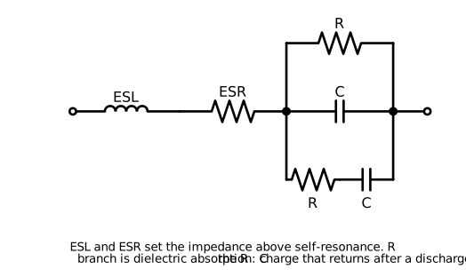 Figure 1. Equivalent circuit of a real capacitor. The series inductance and resistance set the impedance above resonance; the parallel leakage sets the DC loss; the dielectric absorption branch returns charge after a discharge.
A capacitor is a capacitance in series with an inductance and a resistance, with a leakage resistance across it and a slow secondary capacitance that models dielectric absorption. Every parameter is a function of frequency, temperature, voltage, and time, and the datasheet specifies each one under conditions that rarely match the circuit.
Impedance versus frequency
Below the self-resonant frequency the capacitive term dominates and the impedance falls at 20 dB per decade. At resonance the reactances cancel and the impedance equals the ESR. Above resonance the ESL dominates and the impedance rises. The self-resonant frequency is
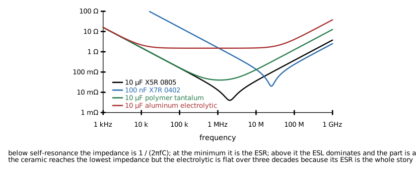 Figure 2. Impedance magnitude versus frequency for four 10 µF or 100 nF parts. The ceramic reaches the lowest minimum; the electrolytic is limited by ESR across three decades.
| Technology | Typical ESR | Typical ESL (part only) | SRF for 10 µF | Notes |
|---|---|---|---|---|
| MLCC 0402 to 1206 | 2 to 20 mΩ | 0.3 to 1 nH | 1 to 3 MHz | Mounting adds 0.5 to 2 nH and dominates |
| Polymer tantalum | 20 to 100 mΩ | 1.5 to 3 nH | 0.5 to 1 MHz | ESR flat with temperature |
| MnO2 tantalum | 0.1 to 3 Ω | 1.5 to 3 nH | 0.3 to 0.8 MHz | ESR rises 2 to 3× at cold |
| Aluminum polymer | 5 to 40 mΩ | 3 to 6 nH | 0.3 to 0.5 MHz | Flat over temperature |
| Aluminum liquid electrolytic | 0.1 to 5 Ω | 5 to 20 nH | 50 to 300 kHz | ESR rises 5 to 10× at -40 °C |
| Film (PP, PET) | 5 to 50 mΩ | 5 to 30 nH | 0.2 to 1 MHz | Depends on lead length and winding |
The ESL in the table is the part alone. Once mounted, the loop through the pads, the vias, and the plane adds inductance that usually exceeds the part's own. A 0402 ceramic with 0.4 nH of internal inductance on a pad with 1 nH of via-to-plane inductance behaves as a 1.4 nH part. Package size, pad geometry, and via placement determine the high-frequency behavior more than the capacitor does.
Loss and dissipation factor
Dissipation factor is the ratio of ESR to reactance at the measurement frequency:
Datasheets give DF at 1 kHz for large values and 1 MHz for small ones. Class 1 ceramics and polypropylene film have DF below 0.1 %; class 2 ceramics 1 to 3 %; aluminum electrolytics 5 to 30 %. Loss matters in three places: it heats the part under AC current, it damps resonances (which is sometimes wanted), and it degrades the Q of a tuned circuit or the accuracy of an integrator.
Leakage
Leakage current is specified as an insulation resistance for ceramics and film (typically above 10 GΩ, or an RC product above 1000 s), and as a current for electrolytics and tantalums, where it is proportional to capacitance and voltage. A 100 µF aluminum electrolytic at rated voltage leaks 10 to 100 µA at 20 °C and several times that at 85 °C. Leakage matters in sample-and-hold circuits, timing circuits, battery-powered hold-up, and any node with a high source impedance.
Dielectric absorption
After a capacitor is discharged and left open, a fraction of the original voltage reappears as charge trapped in the dielectric relaxes back. Dielectric absorption is specified as that fraction. It sets the error floor of sample-and-hold and integrator circuits and the settling time of precision references.
| Dielectric | Dielectric absorption |
|---|---|
| Polypropylene, polystyrene | 0.02 to 0.05 % |
| C0G ceramic | 0.1 to 0.6 % |
| Polyester (PET) | 0.2 to 0.5 % |
| X7R ceramic | 2 to 5 % |
| Aluminum electrolytic | 5 to 15 % |
| Tantalum | 2 to 10 % |
Ceramic capacitors
Multilayer ceramic capacitors are stacks of metal electrodes separated by thin dielectric layers, fired into a monolithic block, with terminations on the ends. Capacitance scales with electrode area, layer count, and dielectric constant, and inversely with layer thickness. The dielectric constant is where the two classes diverge.
Class 1 and class 2
Class 1 dielectrics (C0G, also called NP0, and the lesser-used U2J and C0H) are paraelectric. Their dielectric constant is low, around 10 to 100, so capacitance per volume is small, but it does not depend on voltage, changes with temperature by a specified small coefficient, does not age, and is not piezoelectric. Class 1 parts are available up to about 100 nF in 1206 and a few microfarads in large packages at high cost.
Class 2 dielectrics (X7R, X5R, X6S, X7S, X8R, Y5V, Z5U) are ferroelectric barium titanate. The dielectric constant is 1000 to 10000, so a 0402 package holds 10 µF, but the polarization that gives the high constant is exactly what makes it sensitive to voltage, temperature, time, and mechanical stress.
| Code | Low temperature | High temperature | Capacitance change over range (zero bias) | Class |
|---|---|---|---|---|
| C0G / NP0 | -55 °C | 125 °C | ±30 ppm/°C | 1 |
| U2J | -55 °C | 125 °C | -750 ±120 ppm/°C | 1 |
| X5R | -55 °C | 85 °C | ±15 % | 2 |
| X6S | -55 °C | 105 °C | ±22 % | 2 |
| X7R | -55 °C | 125 °C | ±15 % | 2 |
| X7S | -55 °C | 125 °C | ±22 % | 2 |
| X7T | -55 °C | 125 °C | +22 / -33 % | 2 |
| X8R | -55 °C | 150 °C | ±15 % | 2 |
| Y5V | -30 °C | 85 °C | +22 / -82 % | 2 |
| Z5U | 10 °C | 85 °C | +22 / -56 % | 2 |
The code describes the temperature behavior only, at zero bias. It says nothing about DC bias, and two X7R parts of the same value and rating from different vendors or different package sizes can differ by a factor of two under bias.
DC bias
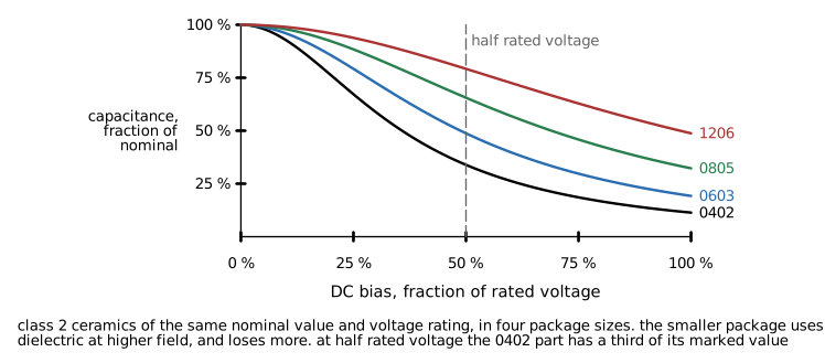 Figure 3. Capacitance versus DC bias for class 2 ceramics of one nominal value and voltage rating in four package sizes. The smaller package has a thinner dielectric at a higher field and loses more.
Applied DC voltage aligns the ferroelectric domains and reduces the dielectric constant. The loss depends on the electric field, which is the voltage divided by the layer thickness. A manufacturer fits more capacitance into a smaller package by making the layers thinner, so the same 10 µF 6.3 V rating in 0402 sees a much higher field at 3.3 V than in 0805, and loses far more.
Representative values at half rated voltage, for X5R and X7R:
| Package | Capacitance remaining at 50 % of rated voltage | At 100 % of rated voltage |
|---|---|---|
| 0201 | 20 to 40 % | 10 to 20 % |
| 0402 | 30 to 50 % | 15 to 30 % |
| 0603 | 45 to 70 % | 25 to 50 % |
| 0805 | 60 to 85 % | 40 to 65 % |
| 1206 | 75 to 90 % | 55 to 80 % |
These are ranges across vendors. The only reliable source is the manufacturer's C-V curve for the specific part number, which every major vendor publishes through an online simulator. The rule that follows: choose the voltage rating so the operating voltage is well below half of it, or choose a larger package, or both, and design with the biased value.
A higher voltage rating in the same package does not always help. A 25 V 0603 part and a 10 V 0603 part of the same capacitance may use the same dielectric thickness with different rating margins, or the 25 V part may use thicker layers and fewer of them. The curve, not the rating, is the specification.
AC voltage and capacitance
Class 2 capacitance also depends on the AC signal amplitude. The datasheet value is measured at 1 V RMS (0.5 V RMS for small values). At the millivolt levels of a signal path the capacitance is 10 to 20 % lower; at large AC swings it rises, then falls. In a filter or a coupling position this is a signal-dependent capacitance, which is a distortion mechanism: a class 2 coupling capacitor in an audio path produces measurable second and third harmonic distortion at low frequencies where the voltage across it is significant.
Temperature
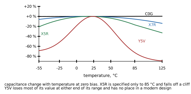 Figure 4. Capacitance change versus temperature at zero bias for C0G, X7R, X5R, and Y5V. The class 2 curves shift and steepen under DC bias.
The temperature coefficient of a class 2 part is not a slope. Capacitance peaks near the Curie temperature of the formulation (near room temperature for most) and falls on both sides. The specified ±15 % for X7R is the envelope over the full range at zero bias; with DC bias the whole curve drops and the shape changes, so the combined bias and temperature loss must be read from the manufacturer's data rather than multiplied from the two separate specifications.
X5R stops at 85 °C. Above that the capacitance falls quickly and the part is out of specification. Boards that operate hot, or hot spots near power components, need X7R or X7S.
Aging
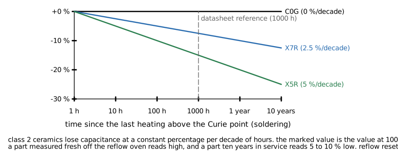 Figure 5. Capacitance versus time after reflow for class 2 ceramics. The loss is logarithmic; the datasheet value is referenced to 1000 hours.
Ferroelectric domains relax over time, and class 2 capacitance falls by a constant percentage per decade of hours after the last time the part was heated above its Curie temperature. Typical rates:
| Dielectric | Aging rate |
|---|---|
| C0G | 0 |
| X7R, X7S | 1 to 2.5 % per decade hour |
| X5R, X6S | 2 to 7 % per decade hour |
| Y5V, Z5U | 5 to 10 % per decade hour |
The marked value is the value at 1000 hours. A part measured one hour after reflow reads 5 to 15 % high on the same basis; a part in service for 10 years (about 10^5 hours) reads 5 to 10 % below marked. Reflow above about 125 °C de-ages the part and restarts the clock, which is why incoming inspection of aged parts shows low values that recover after assembly, and why a rework on one capacitor changes its value relative to its neighbors.
Piezoelectric and microphonic effects
Barium titanate is piezoelectric. A class 2 capacitor under AC voltage vibrates and can sing audibly (the whine from a converter with a large ceramic output capacitor at an audible switching or burst frequency). The reverse also holds: mechanical vibration or shock applied to a class 2 part with DC voltage across it generates a voltage. In a low-noise amplifier input, a reference bypass, or a high-impedance sensor node, a class 2 capacitor is a microphone. Class 1 ceramics and film are not piezoelectric.
Mitigations for singing: a lower-dielectric-constant part (X7R sings less than X5R at the same value), a larger package with less strain per volt, two parts in series or on opposite sides of the board so their strains cancel, film or polymer parts for the offending value, or moving the switching or burst frequency out of the audible band.
Cracking
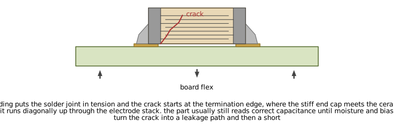 Figure 6. Cross-section of a flex crack. Board bending puts the termination in tension and the crack starts at the termination edge and runs diagonally through the electrode stack.
Ceramic is brittle. Two mechanisms crack it.
Flex cracks come from bending the board after the part is soldered: depaneling, screwing the board into a housing, connector insertion, pressing a button, or a bowed board pulled flat by screws. The stiff solder joint and termination hold the ends while the board bends under the body, and the crack starts at the inner edge of the termination. Larger packages are more vulnerable because they span more of the bend; 1206 and larger parts are the usual casualties, and 0402 and smaller rarely flex-crack.
Thermal shock cracks come from heating the part faster than the ceramic can equalize: hand soldering a large MLCC with an iron, wave soldering without preheat, or a reflow profile with too steep a ramp. The crack forms internally and is invisible.
A cracked part may measure correctly. The crack becomes a failure when moisture and DC bias drive electrochemical migration along it, over days to months, and the part turns first leaky and then short. On a power rail a shorted ceramic is a fault current path; on a battery-powered product it is a dead battery or a fire.
Mitigations, in order of effectiveness:
- Keep MLCCs out of high-stress zones: within about 5 mm of board edges, V-scores, tab routes, mounting holes, and connectors, and away from anywhere the board is pressed. See Figure 9, and Whole-board flex below for the board's own bending.
- Orient the long axis of the part parallel to the bend line (parallel to the nearest edge or score), which puts less differential strain across the terminations.
- Use soft-termination parts (a conductive polymer layer between the termination and the ceramic that absorbs strain; every major vendor offers them) for parts that must sit near stress or that would cause a hazard if shorted.
- Use open-mode or series-electrode construction for parts on a battery or mains-derived rail, where a short is a safety event. Open-mode parts keep the electrodes away from the termination edge so a flex crack does not bridge them; series-electrode parts are two capacitors in series inside one body, so one crack does not short the part.
- Put two parts in series on a critical rail if the safety case requires it.
- Use a smaller package: two 0603 parts in place of one 1206.
- Control the depaneling method (a router or a laser rather than breaking a V-score by hand) and the assembly torque.
- Never hand-solder an MLCC larger than 0603 without preheating the board.
Whole-board flex
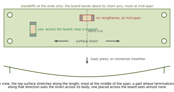 Figure 7. A long, narrow board supported at its ends bends about its short axis. Surface strain runs along the length and peaks at mid-span, so a capacitor placed lengthwise there takes the full strain across its terminations.
Edge zones are not the only source of bending. The board as a whole flexes whenever it is loaded between supports, and its shape sets the direction. A long, narrow board, a board supported only at its ends, and a board with a connector that is mated by hand all bend about their short axis: the surface stretches along the length, most at the middle of the span, and the bend line runs across the width. A square board supported at four corners bends in both directions, and a cantilevered board (a mezzanine or a card supported along one edge) bends most at its root, where it meets the support.
Consequences for placement:
- Identify the flex axis from the aspect ratio and the mounting before placing large ceramics. On a long, narrow board the long axis of every MLCC of 0805 or larger should run across the board, parallel to the short edge, so it sits parallel to the bend line.
- Keep large ceramics away from the middle of an unsupported span and away from the root of a cantilever. Near a standoff or a stiff edge the curvature is small.
- Add standoffs, a stiffener, or a support rib where a large MLCC must sit in a high-curvature region, and specify the maximum board deflection in the mechanical drawing if the enclosure can press on the board.
- The same applies during assembly: a long board held at one end while a connector is pressed in at the other has been bent, and the in-circuit test fixture that pushes pogo pins into it has bent it again. Fixture supports go under the largest ceramics.
- Boards that will be flexed in service (press-fit, handheld, anything with a keypad) should specify soft-termination or open-mode parts for every MLCC of 0805 and larger regardless of placement.
Voltage rating and derating
Class 2 ceramics do not have a hard derating rule the way tantalum does; the rated voltage can be applied continuously without a wear-out mechanism, and the failure rate rises with voltage and temperature in the usual way. The derating is set by capacitance: the operating voltage must be low enough on the C-V curve that the remaining capacitance does the job. In practice that means operating at 30 to 50 % of rated voltage for capacitance-critical positions and up to 80 % for positions where any capacitance is enough. Automotive and industrial guidelines commonly require 50 % for class 2 ceramics on rails that see transients.
Class 1 ceramics have no bias dependence and are used up to 80 % of rating with the same transient margin considerations as any other part.
What ceramics are good for
- Decoupling and bypass at every frequency above a few hundred kilohertz, where nothing else has the impedance.
- Switching converter input and output filters, with the value computed at bias and the ripple current rating (a thermal limit, usually generous) checked.
- Timing, filters, sample-and-hold, and precision analog: C0G only.
- Snubbers and resonant circuits at high frequency: C0G, and the AC current rating must be checked because ceramics have a small thermal mass.
- Any position where low ESR, small size, and no polarity matter and the biased value is acceptable.
Aluminum electrolytic capacitors
An aluminum electrolytic uses an etched aluminum foil anode with an anodized oxide dielectric, and a cathode that contacts the oxide through either a liquid electrolyte, a solid conductive polymer, or both (hybrid). The oxide is thin and the etched foil has an enormous surface area, so capacitance per volume is high and the parts are cheap. The dielectric is polar: reverse voltage beyond about 1 V dissolves the oxide.
| Type | ESR (100 µF, 25 V class) | Ripple current | Leakage | Life | Cold behavior | Cost |
|---|---|---|---|---|---|---|
| Liquid electrolyte | 0.1 to 2 Ω | Low to moderate | Low | 1000 to 10000 h at rated T | ESR ×5 to ×10 at -40 °C | Lowest |
| Solid polymer | 5 to 40 mΩ | High | Higher (×10) | Long, no dry-out | Nearly flat | Higher |
| Hybrid polymer | 20 to 60 mΩ | High | Low | Long | Flat to -40 °C | Higher |
Liquid electrolyte parts
The liquid electrolyte is the part's cathode and also its weakness. It evaporates through the seal, and as it does, ESR rises and capacitance falls until the part is out of specification. The rate follows an Arrhenius relation, and the rule of thumb is that life doubles for every 10 °C below the rated temperature:
where L0 is the rated life at rated temperature (the "2000 h at 105 °C" on the datasheet) and Tcore is the actual core temperature, which is the ambient plus the self-heating from ripple current through the ESR. A 2000 h, 105 °C part at a 55 °C core temperature has an expected life of 2000 × 2^5 = 64000 hours, about 7 years of continuous operation. The same part at 85 °C has 8000 hours, less than a year. The manufacturer's calculator includes the ripple heating term and the voltage derating term and should be used in place of the rule of thumb.
End of life for a liquid electrolytic is a specified drift: typically capacitance down 20 to 30 %, ESR up by a factor of two to three, and leakage above the initial limit. The part does not usually fail catastrophically at end of life; it stops filtering, and the circuit it filters fails. The exception is reverse voltage, overvoltage, or excessive ripple, which generate gas until the vent opens and the part expels electrolyte.
Leakage current rises with temperature and time in storage. A liquid electrolytic that has sat unpowered for years has a degraded oxide and draws high leakage when first powered until the oxide re-forms. Parts stored more than two years should be reformed with a current-limited supply before use, and a product that will sit in inventory should specify long-shelf-life parts.
Polymer and hybrid parts
Solid polymer aluminum capacitors replace the liquid with a conductive polymer. ESR is a few tens of milliohms, flat over temperature, and there is no dry-out mechanism, so life is set by the polymer's slow oxidation and is much longer. The costs are higher leakage (tens to hundreds of microamps), lower voltage ratings (typically to 100 V, commonly 35 V and below), a tighter limit on overvoltage and surge, and price. Polymer parts fail short under sustained overvoltage, which matters on a rail with transients.
Hybrid parts use polymer with a small amount of liquid electrolyte, which heals oxide defects and keeps leakage low, at the cost of a slightly higher ESR than pure polymer and a return of the temperature dependence at the extreme cold end. They are the current default for automotive and industrial rails where low ESR, low leakage, and long life are all needed.
What aluminum electrolytics are good for
- Bulk energy storage: hold-up through a supply interruption, the input reservoir of a mains-powered supply, and the input of a converter fed through a long cable, where the capacitor absorbs the cable's inductive energy.
- Low-frequency filtering below about 100 kHz where the capacitance per cost is unmatched.
- Damping. A liquid electrolytic's ESR in parallel with a ceramic bank damps the LC resonance of an input filter, which a pure ceramic bank does not.
- Positions where a fail-open at end of life is acceptable and a shorted part is not.
Derating
Operate liquid electrolytics at or below 80 % of rated voltage for life, and at a ripple current below the rated value adjusted by the datasheet's frequency and temperature multipliers. Polymer parts are commonly derated to 80 to 90 % of rating and must not see transients above rating. Both types should be selected for a core temperature that meets the life target, which usually means the largest can that fits rather than the smallest that meets the capacitance.
Tantalum capacitors
A tantalum capacitor is a sintered tantalum powder anode with a tantalum pentoxide dielectric and a cathode of either manganese dioxide or conductive polymer. The oxide is thin and stable, the powder has a large surface area, and the result is high capacitance per volume in a low-profile surface-mount package with no wear-out mechanism. Tantalums do not age and their capacitance is nearly independent of voltage and temperature.
Manganese dioxide tantalum
The MnO2 cathode has a failure mode that defines the technology. A defect in the oxide carries current, the local heating converts the MnO2 to a lower oxide that is conductive, the fault grows, and the tantalum anode ignites in the oxygen released by the MnO2. An MnO2 tantalum fails short and, with a low-impedance source, burns. The failure rate is strongly voltage dependent, and the traditional derating rules follow:
- Operate at 50 % of rated voltage or less. Below 50 % the failure rate falls by roughly a factor of ten for each further 10 % of derating.
- Limit the surge current with series impedance. The traditional rule for a low-impedance source is at least 1 Ω per volt of applied voltage in series for full reliability, or accept a higher failure rate with 0.1 Ω per volt. On a converter output this is often impractical, and polymer parts are used instead.
- Do not use MnO2 tantalum directly across a battery or a low-impedance rail without series resistance or a fuse.
- ESR rises by a factor of two to three at -40 °C and the ripple current rating is low.
Polymer tantalum
The polymer cathode does not release oxygen and self-heals by becoming non-conductive at a defect. Polymer tantalums are benign in failure, tolerate surge current, have an ESR of tens of milliohms that is flat over temperature, and can be derated to 80 to 90 % of rating. Leakage is higher than MnO2 and the voltage ratings are lower (commonly to 35 V, with 50 to 75 V available). Polymer tantalum has replaced MnO2 in most new designs where the cost is acceptable.
Niobium oxide
Niobium oxide capacitors are a lower-cost relative of MnO2 tantalum with a benign failure mode (they fail to a high resistance rather than a short). Capacitance per volume and voltage ratings are lower. They are a drop-in for MnO2 tantalum in low-voltage positions where the ignition risk is unacceptable and polymer is too costly.
What tantalums are good for
- Bulk capacitance in a thin profile where an electrolytic can does not fit.
- Positions needing a stable value over temperature with moderate ESR: filters below 100 kHz, hold-up, and reference bypass where the microphonic effect of a ceramic is a problem.
- Damping a ceramic bank, using the ESR of a polymer tantalum in parallel.
- Long-life products, since there is no dry-out.
The polarity mark on a surface-mount tantalum is a stripe on the positive end, the opposite convention from an aluminum electrolytic (stripe on negative). Reverse polarity beyond a small fraction of rated voltage destroys the part, and a reversed MnO2 tantalum is an ignition source.
Film capacitors
Film capacitors use a polymer dielectric with either a metal foil electrode or a thin metallized layer deposited on the film. They have no voltage coefficient, no aging, no piezoelectric effect, tolerances to 1 %, and losses from very low (polypropylene) to moderate (polyester). Their size per microfarad is the largest of any technology, and above a few microfarads they become expensive and large.
| Dielectric | Temperature range | Temperature coefficient | DF at 1 kHz | Dielectric absorption | Use |
|---|---|---|---|---|---|
| Polypropylene (PP) | -55 to 105 °C | -200 ppm/°C | 0.02 % | 0.05 % | Snubbers, resonant, DC link, precision, audio |
| Polyester (PET) | -55 to 125 °C | +400 ppm/°C, nonlinear | 0.5 % | 0.3 % | General coupling and decoupling, low cost |
| Polyphenylene sulfide (PPS) | -55 to 140 °C | ±100 ppm/°C | 0.05 % | 0.1 % | Precision at high temperature, reflowable SMD |
| Polyethylene naphthalate (PEN) | -55 to 125 °C | +300 ppm/°C | 0.4 % | 0.3 % | SMD general purpose |
| Acrylic | -55 to 125 °C | ±200 ppm/°C | 0.5 % | 0.2 % | SMD, moderate precision |
Metallized film capacitors self-heal: a dielectric breakdown vaporizes the thin electrode around the fault and isolates it, at a small loss of capacitance. Foil-electrode parts do not self-heal but handle far higher peak currents. A metallized part at the end of its life has lost capacitance from accumulated clearings and, in humid conditions, from corrosion of the metallization; the specification is a capacitance drift, and moisture resistance grades matter for outdoor or unsealed products.
Safety capacitors
Capacitors that bridge mains to earth (Y class) or mains line to line (X class) must be rated to the safety standard (IEC 60384-14) for the position, because their failure mode is a shock or fire hazard.
| Class | Position | Failure requirement | Peak pulse rating |
|---|---|---|---|
| X1 | Line to line | Fail short acceptable, must not ignite | 4 kV |
| X2 | Line to line | Same | 2.5 kV |
| Y1 | Line to earth, reinforced | Must not fail short | 8 kV |
| Y2 | Line to earth, basic | Must not fail short | 5 kV |
Y capacitors are limited in value by the allowed earth leakage current of the product class (a few nanofarads for equipment with a protective earth, less for double-insulated). Both classes are usually film for X and either film or a specially rated ceramic for Y. An ordinary capacitor of adequate voltage rating in an X or Y position is a compliance failure and a hazard.
Other technologies
Supercapacitors (electric double-layer) offer farads in a small can at 2.5 to 3 V per cell, with high ESR (tens of milliohms to ohms), high leakage, and a life that falls sharply above rated voltage and temperature. Cells in series need balancing. They are energy storage for hold-up and pulse loads, not filters.
Mica and glass capacitors are precision class 1 parts for RF and high-voltage pulse work, stable and low-loss, large and expensive. Modern C0G ceramics have replaced them in most positions below 1 kV.
Silicon capacitors are thin-film parts on a silicon substrate with class 1 stability, very low ESL, and small values. They serve RF and high-speed decoupling at the die or module level.
Selection by circuit function
| Function | First choice | Also acceptable | Avoid | What matters |
|---|---|---|---|---|
| High-frequency decoupling (above 1 MHz) | Class 2 MLCC, smallest package that gives the biased value | - | Anything with leads | ESL, mounting inductance, placement at the pin |
| Bulk decoupling (10 kHz to 1 MHz) | Class 2 MLCC in 0805 to 1210 | Polymer tantalum, polymer aluminum | Liquid electrolytic (ESR too high at cold) | Biased capacitance, ESR for damping |
| Hold-up and energy storage | Aluminum electrolytic (liquid or hybrid) | Polymer tantalum in low profile | Class 2 MLCC (bias loss, cost per joule) | Energy at the usable voltage window, leakage, life |
| Converter input filter | MLCC bank plus one electrolytic for damping | Polymer aluminum | Bare MLCC bank on a long cable (undamped resonance) | Ripple current, biased C, damping |
| Converter output filter | MLCC bank; polymer for damping if the control loop needs ESR | Polymer aluminum or tantalum | Liquid electrolytic where ESR sets ripple | Biased C, ESR versus loop design, ripple |
| LDO output | Whatever the datasheet's ESR window allows, usually MLCC | Polymer tantalum for older LDOs needing ESR | Liquid electrolytic on ceramic-stable LDOs (too much ESR at cold) | ESR range over temperature, minimum C at bias |
| Timing (RC, 555, PLL loop filter) | C0G | PP or PPS film | Class 2 MLCC | Tolerance, TC, aging, dielectric absorption |
| Active and passive filters | C0G below 100 nF, film above | PPS for SMD film | Class 2 MLCC | Tolerance, distortion, TC |
| AC coupling in an audio or precision path | Film (PP, PET) or C0G | Large class 2 MLCC only if the voltage across it is negligible | Class 2 MLCC with signal voltage across it, electrolytic in the signal path | Distortion, leakage, dielectric absorption |
| Sample-and-hold, integrator | PP, PS, or C0G | PPS | Class 2, electrolytic, PET | Dielectric absorption, leakage, TC |
| Reference bypass | C0G or film | Polymer tantalum | Class 2 MLCC in a low-noise or vibration position | Microphonics, leakage, DA settling |
| Snubber | PP film or C0G | - | Class 2 (heating, value shift) | Pulse current, dV/dt, dissipation |
| Resonant tank, LLC, wireless power | PP film or C0G with an AC current rating | - | Class 2 | AC current, loss, stability |
| Crystal load | C0G | - | Class 2 | Tolerance, TC (a 10 % shift moves the frequency) |
| X and Y safety positions | Rated X or Y film or ceramic | - | Anything unrated | Standard compliance, leakage current |
| High voltage DC link | PP film | Liquid electrolytic in series with balancing | - | Ripple current, self-healing, voltage margin |
Decoupling in more detail
The purpose of a decoupling capacitor is to be a low impedance between a power pin and its ground pin over the frequency band where the device draws transient current. That impedance is set by the capacitor's ESL plus the mounting inductance up to the frequency where the plane takes over, and by the capacitance only below the self-resonant frequency. Consequences:
- A capacitor 10 mm from the pin has 5 to 10 nH of trace inductance in series with it and is not decoupling anything above a few megahertz. Placement at the pin with the shortest via to the plane is the specification.
- The smallest package with an adequate biased value gives the lowest ESL. A 0402 100 nF part is a better decoupling capacitor than a 0805 100 nF part.
- Multiple capacitors of the same value in parallel divide the ESL and ESR. Multiple capacitors of widely different values create anti-resonances (Figure 8).
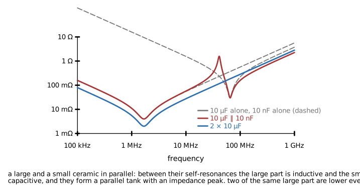 Figure 8. Impedance of a 10 µF and a 10 nF ceramic in parallel, compared to two 10 µF parts. Between the two self-resonances the pair forms a parallel tank with an impedance peak.
The traditional decade-spaced set (10 µF, 1 µF, 100 nF, 10 nF) was a response to the high ESL of leaded parts and to the ESR that damped the anti-resonances. With modern MLCCs the ESR is low, the anti-resonance peaks are sharp, and a bank of the same value in the smallest package is usually the lower impedance. Where a mixed set is used, keep the values within a factor of ten of each other and confirm the impedance with the manufacturer's models.
Derating summary
| Technology | Voltage | Temperature | Ripple and AC current | Other |
|---|---|---|---|---|
| Class 1 MLCC | 80 % of rating, transient margin | Full rated range | Check for resonant and snubber duty | None |
| Class 2 MLCC | Set by the C-V curve; 30 to 50 % for value-critical positions, 50 % where transients occur | X5R to 85 °C, X7R to 125 °C, with C-T curve applied | Check self-heating in snubber and resonant duty; usually not limiting for filtering | Aging, piezo, flex cracking, placement rules |
| Aluminum liquid electrolytic | 80 % of rating | Core temperature set by the life target; life doubles per 10 °C below rating | At or below rated ripple with frequency and temperature multipliers | Shelf life, reforming, vent orientation |
| Aluminum polymer | 80 to 90 % of rating, no transients above rating | Rated range, life per datasheet | Rated ripple | Higher leakage, fails short on overvoltage |
| Aluminum hybrid | 80 to 90 % | Rated range | Rated ripple | None specific |
| MnO2 tantalum | 50 % of rating or less | Rated range, ESR ×2 to ×3 at cold | Low rated ripple | Series impedance, fails short and ignites |
| Polymer tantalum | 80 to 90 % | Rated range | Rated ripple | Higher leakage |
| Film | 80 % of DC rating; AC rating separately | Rated range; PET and PP derate above 85 °C | dV/dt and RMS current ratings | Humidity grade for metallized parts |
| Supercapacitor | 80 to 90 % of cell rating with balancing | Life halves per 10 °C | ESR heating | Leakage, balancing |
Reliability and failure modes
| Technology | Dominant failure mode | Result | Common cause |
|---|---|---|---|
| Class 2 MLCC | Flex crack, thermal shock crack | Short (after moisture and bias) | Depaneling, mounting, hand soldering, board flex |
| Class 1 MLCC | Same, rarer | Short | Same |
| Aluminum liquid | Dry-out | Drift out of spec (high ESR, low C) | Temperature, ripple, time |
| Aluminum liquid | Gas generation | Vent, electrolyte leak | Reverse voltage, overvoltage, excessive ripple |
| Aluminum polymer | Oxide breakdown | Short | Overvoltage, surge |
| MnO2 tantalum | Oxide defect and thermal runaway | Short, ignition | Surge current, voltage, reverse polarity |
| Polymer tantalum | Oxide defect | High resistance or benign short | Overvoltage |
| Metallized film | Clearing accumulation, corrosion | Capacitance loss | Humidity, voltage, temperature |
| Foil film | Dielectric puncture | Short | Overvoltage, dV/dt |
| Supercapacitor | Electrolyte decomposition | ESR rise, capacitance loss, swelling | Overvoltage, temperature |
The design consequence: a technology that fails short needs the circuit around it to survive a short. A shorted ceramic on a 12 V rail fed from a 10 A supply dissipates whatever the trace resistance allows, and traces have burned. A fuse, a current-limited source, or a series-electrode part on any rail where a short is a safety event is part of the capacitor selection.
Layout and assembly
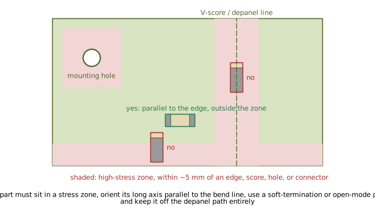 Figure 9. Board regions where flex stress concentrates, and MLCC orientation relative to a board edge. A part in the stress zone with its long axis across the bend line is the one that cracks.
Ceramics
- Keep MLCCs, especially 0805 and larger, at least 5 mm from board edges, V-scores, breakaway tabs, mounting holes, and press-fit or high-insertion-force connectors.
- Orient the long axis parallel to the nearest edge or score line, and on a long, narrow board across the board's length (parallel to the short edge), since the board bends about its short axis.
- Keep large ceramics away from the mid-span of a board supported only at its ends and from the root of a cantilevered board, and put test fixture supports under them.
- Do not place large MLCCs under or beside a part that is screwed down, or on a board region that will be pressed during assembly or use (buttons, card edges).
- Use pads sized to the vendor recommendation. Oversized pads pull more solder into the fillet, stiffen the joint, and raise flex stress; undersized pads tombstone.
- Route depaneling with a router or laser where possible. A hand-broken V-score is the single largest source of flex cracks.
- Follow the reflow profile ramp limits (typically 2 to 3 °C per second) and preheat before any wave or hand soldering. Hand soldering of 1206 and larger parts should be done with a hot-air tool or with the board preheated to 100 °C or more.
- Pair a soft-termination or open-mode part with any position that must sit in a stress zone.
Electrolytics
- Orient the vent away from anything that would be damaged by electrolyte and away from the user.
- Keep liquid electrolytics away from heat sources; every 10 °C halves the life. The hottest part of the board is the worst place for the bulk capacitor.
- Provide the polarity mark on the silkscreen unambiguously, and note the opposite convention for tantalum.
- Cleaning agents and conformal coating can attack the seal on some electrolytics; check the datasheet's chemical compatibility.
Film and safety parts
- Y capacitors need creepage and clearance to the safety standard on both sides, which the footprint must provide.
- Large film parts have mass; on a board that sees vibration they need mechanical support or adhesive.
Reading the datasheet
The datasheet parameters that decide whether a capacitor works in its position:
- C-V curve (class 2 ceramics). Read the capacitance at the operating voltage. If the datasheet does not show it, use the vendor's online simulator, and if that does not exist, choose another vendor.
- C-T curve, ideally at the operating bias. The code letter is the zero-bias envelope only.
- Impedance and ESR versus frequency, at the operating temperature for electrolytics. The 100 kHz or 120 Hz single number is not enough for a converter.
- Ripple current rating with its frequency and temperature multiplier tables, and the self-heating limit (electrolytic, tantalum) or the AC current rating (film, ceramic in resonant duty).
- Life specification: hours at rated temperature and ripple, and the end-of-life criteria. Apply the manufacturer's life calculator.
- Leakage current at the operating temperature, and its time behavior.
- Surge and transient ratings, particularly for polymer and tantalum parts.
- Aging rate for class 2 ceramics, where the application is sensitive to it.
- Termination type (standard, soft, open-mode) and the flex test result (the vendor's board bend test in millimeters of deflection).
- Moisture sensitivity level for polymer and film SMD parts, which sets storage and baking requirements before reflow.
Design procedure
- Define what the capacitor must do: the minimum capacitance at the operating point, the frequency band, the maximum impedance or ESR, the ripple or AC current, the voltage including transients, the temperature range, the life target, and the failure consequence.
- Pick the technology from the function table, then check the failure mode against the failure consequence and add series impedance, a fuse, or a fail-safe part construction if needed.
- For class 2 ceramics: choose the package and rating, read the C-V curve at the operating voltage, apply the temperature curve at that bias, subtract the aging over the product life, and confirm the minimum capacitance is still met. If not, go up in package, up in rating, or to parallel parts.
- For electrolytics: choose the case for the ripple current and the life target at the actual core temperature, then check that the capacitance and ESR at the coldest operating temperature meet the circuit's needs.
- For tantalum: derate the voltage per the type, check surge current and add series impedance if the source is stiff, and confirm the polarity marking.
- For film: confirm the AC voltage and dV/dt ratings for pulse duty, the humidity grade, and the physical size and mounting.
- Check the impedance curve of the mounted part, with the mounting inductance, over the frequency band. For decoupling, check the parallel bank for anti-resonances.
- Place the part with the mechanical and thermal constraints applied: stress zones, orientation, heat sources, vent direction, creepage.
- Record the biased capacitance and the vendor part number as design constraints, since a second-source substitution of the same marked value can have half the capacitance in the circuit.
Worked example: output capacitor of a 3.3 V buck converter
A synchronous buck delivers 3.3 V at 2 A from 12 V at 800 kHz with a 4.7 µH inductor. The required output capacitance for a 20 mV ripple and a 100 mV droop on a 1 A load step is calculated at 44 µF. The ambient is 60 °C, the product life is 10 years, and the converter's control loop is designed for a ceramic output with no ESR zero.
Technology. A ceramic bank. The loop wants low ESR; the ripple current (about 0.3 A RMS) is trivial for MLCCs; and the value is small enough. A liquid electrolytic is ruled out by ESR and by life at 60 °C ambient next to the inductor.
Candidate. 22 µF X5R 6.3 V 0805, two in parallel for a 44 µF nominal.
DC bias. The vendor curve for that part at 3.3 V (52 % of rating) shows 55 % of nominal: 12.1 µF each, 24.2 µF for the pair. Not enough.
Temperature. The converter runs the capacitors at about 75 °C. X5R at 75 °C and 3.3 V bias reads a further 10 % down on the vendor's combined curve: 21.8 µF for the pair.
Aging. Ten years is 8.8 × 10^4 hours, 1.9 decades past the 1000 h reference. At 5 % per decade the loss is 9.5 %: 19.7 µF at end of life. Less than half the requirement.
Revised candidate. 22 µF X7R 10 V 1210. The vendor curve at 3.3 V (33 % of rating) shows 85 %: 18.7 µF each. X7R at 75 °C and bias: another 5 %, 17.8 µF. Aging at 2.5 % per decade over 1.9 decades: 4.8 %, 16.9 µF each at end of life. Three parts give 50.7 µF at end of life, above the 44 µF requirement, with the X7R rating covering the temperature and the 1210 package requiring a placement at least 5 mm from any edge or hole, oriented parallel to the nearest edge. Three 1210 parts are also cheaper and lower in profile than the five 0805 6.3 V parts that would otherwise be needed.
Alternative. One 47 µF polymer aluminum at 6.3 V, 25 mΩ ESR, in parallel with one 10 µF X7R 0805 for high frequency. The polymer's ESR is stable over temperature and adds a zero that the loop was not designed for, so this option needs the compensation re-checked. It does not have the bias loss or the flex-crack risk, and it is the better choice if the board region is stressed or the part will be hand-assembled.
Record. The bill of materials carries the vendor part number with a note that the alternate must show at least 16 µF at 3.3 V and 75 °C on its own C-V curve, and the layout carries the stress-zone constraint.
Design errors
- Output capacitance computed from the marked value. Correction: use the biased value from the C-V curve, at temperature, at end of life.
- 0402 ceramics chosen for a bulk position to save space. Correction: the biased value in 0402 is a fraction of the marking; use 0805 or larger, or polymer.
- X5R on a board that runs above 85 °C. Correction: X7R or X7S.
- Class 2 ceramic in a filter, timer, or crystal load. Correction: C0G or film.
- Class 2 ceramic across an audio signal. Correction: film or C0G, or a large enough class 2 value that the voltage across it is negligible at the lowest frequency.
- Large MLCC at the board edge or under a screw. Correction: move it, reorient it, and use a soft-termination part if it cannot move.
- Liquid electrolytic as the sole output capacitor of a ceramic-stable LDO or converter. Correction: ceramic for the loop, electrolytic in parallel only where the loop tolerates the ESR.
- Electrolytic life calculated at ambient. Correction: core temperature, which includes ripple heating and the neighbor components.
- MnO2 tantalum directly on a battery or a stiff rail. Correction: polymer tantalum, or series resistance and derating to 50 % or less.
- Tantalum installed by the electrolytic polarity convention. Correction: stripe is positive on tantalum; confirm the silkscreen.
- Decade-spaced decoupling set with modern MLCCs. Correction: multiple parts of the same value in the smallest package, or values within a factor of ten, checked against the impedance model.
- Unrated capacitor in an X or Y position. Correction: an X or Y rated part with the creepage its footprint requires.
- Second source substituted by marked value. Correction: the design constraint is the biased capacitance; alternates are qualified against the C-V curve.
- Aged class 2 parts failing incoming inspection. Correction: measure after de-aging (a reflow or 150 °C for an hour) or apply the aging correction to the limit.
Limitations of this document
- The C-V, C-T, and aging curves in the figures are representative models. Real parts vary by vendor, formulation, and lot, and the manufacturer's data for the specific part number governs.
- ESR and ESL values in the tables are typical ranges for the package and technology and are not a substitute for the part's impedance curve.
- The derating percentages are industry conventions and common guideline values, not standards; automotive, aerospace, and medical product requirements set their own.
- The flex crack discussion reflects typical MLCC construction. Vendor-specific soft-termination and open-mode designs differ in their tested bend performance.
- Safety capacitor classes are summarized from IEC 60384-14; the standard and the product standard govern the allowed values and positions.