Connectors and Cables
noteSelecting and specifying connectors and cable assemblies: contact resistance and where it comes from, current rating and its derating with temperature and loaded positions, plating and mating cycles, wire ampacity and voltage drop, crimp versus solder and how a crimp is qualified, connector families by use, shielded cable termination and why pigtails fail, locking and strain relief, sealing and environment, and the failure modes that end up as intermittents.
related tools: wire gauge (awg), cable voltage drop, awg wire table, creepage & clearance (iec 60664-1, ipc-2221b)
Scope: board-to-wire, board-to-board, and cable connectors and their cable assemblies for signal and power up to a few hundred volts and a few tens of amps. The note covers electrical ratings and their derating, contact physics, wire selection, termination methods and their qualification, shielding, mechanical and environmental requirements, and failure modes. RF coaxial connectors above 1 GHz, fiber, and mains plugs are mentioned only for the rules that carry over.
Common errors
- Reading the current rating as a continuous rating. It is the current for a 30 °C rise on one energized contact at room ambient. Loading every position, raising the ambient, and enclosing the connector each take a fraction away.
- Choosing a connector by pin count and pitch. The contact system (normal force, plating, mating cycles, wire gauge range) is what decides whether it works for the life of the product.
- Soldering wires into a connector meant for crimps. Solder wicks up the strands, the stiff section fatigues at the wick boundary, and the joint fails in vibration.
- Crimping with the wrong tool. A crimp is a controlled cold weld between strands and barrel; it needs the terminal manufacturer's die geometry and crimp height. Generic pliers make a mechanical grip with high, unstable resistance.
- Terminating a shield with a pigtail. The shield's job is to be a continuous surface; a pigtail turns it into an inductor and the cable into an antenna.
- Tin-plated contact mated with gold. Gold against tin wears the tin and drives fretting corrosion; plating is matched.
- No strain relief. Wire flexing at the crimp or solder joint is the most common cable failure.
- Ignoring the mating cycle rating. A 25-cycle board-to-board connector on a product that is opened for service will not last.
Contact physics
 Figure 1. The resistance chain through a mated contact. The interface terms, constriction and film, are the ones that change with wear, corrosion, and normal force.
The resistance from wire to board through a mated connector is the sum of the termination (crimp or solder), the bulk of each contact, and the interface between the two contacts. The interface is the interesting part. Two metal surfaces touch only at asperities, a few real contact spots whose total area is far smaller than the apparent area. Current constricts through those spots (constriction resistance), and any oxide, sulfide, or contaminant film on them adds film resistance.
Contact resistance is specified per contact, typically 5 to 30 mΩ initial for a good signal contact and 0.5 to 5 mΩ for a power contact, with an allowed increase after the environmental and mating tests (often 10 to 20 mΩ). What keeps it low:
- Normal force. Higher force means more and larger contact spots and the ability to break through films. Signal contacts use 0.5 to 1.5 N; power contacts several newtons. Force falls with spring relaxation at temperature and with wear.
- Plating. Gold does not oxidize, so a gold interface has no film and stays low at low force; it wears through to the nickel underplate with mating cycles, which is why cycle ratings scale with gold thickness. Tin oxidizes, but the oxide is brittle and the wipe during mating breaks it; tin needs more force and is vulnerable to fretting.
- Wipe. The sliding motion during mating scrapes the surfaces clean. Contacts designed with wipe self-clean at each mating; a contact that mates without wipe (some press-fit and zero-insertion-force types) relies on plating alone.
- Gas-tight interface. A contact with enough force excludes air from the contact spots, and they do not corrode. Low-force contacts and tin contacts in vibration lose this.
Fretting
A tin-plated contact under vibration or thermal cycling moves by micrometers at the interface. Each motion exposes fresh tin, which oxidizes; the oxide debris accumulates in the contact spot, and the resistance climbs from milliohms to ohms over months. This is fretting corrosion, the mechanism behind most intermittent connectors in vehicles and industrial equipment. It is prevented by locking the housings so the contacts cannot move relative to each other, by higher normal force, by gold plating on both sides, or by contact lubricant. A tin contact that is never disturbed lasts; one that vibrates fails.
Plating combinations
| Mating pair | Result |
|---|---|
| Gold to gold | Lowest and most stable resistance, best for low-level signals, most mating cycles. Cost. |
| Tin to tin | Acceptable for power and for signals above about 5 V and 10 mA, with adequate force and no fretting. Cheapest. |
| Gold to tin | Not recommended: gold is hard and abrades the tin, tin transfers to the gold, and fretting follows. |
| Silver to silver | Power contacts; low resistance, tarnishes to a conductive sulfide. |
| Nickel underplate | Present under gold and tin on good contacts as a diffusion barrier; gold without nickel fails in months. |
Gold thickness is the specification behind the cycle rating: gold flash (0.05 to 0.1 µm) for 10 to 50 cycles, 0.4 µm for a few hundred, 0.75 µm and up for thousands. Selective plating (gold on the contact area only) is normal and fine.
Dry circuit: a contact that carries a signal below about 20 mV or 1 mA cannot break through a film electrically, because there is not enough voltage to puncture the oxide. Such a signal needs gold, or a wetting current deliberately added.
Current rating and derating
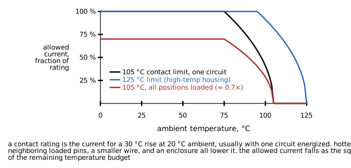 Figure 2. Allowed contact current versus ambient temperature for a 105 °C contact limit, a 125 °C limit, and with all positions loaded. The allowed current falls as the square root of the remaining temperature budget.
A connector's current rating is a temperature-rise rating: the current, through a specified wire, that produces a 30 °C rise (sometimes 20 or 45 °C) at 20 °C ambient, usually with a single circuit energized, measured per a standard such as IEC 60512 or EIA-364. The contact's temperature limit is the housing material's, typically 105 °C for nylon and 125 °C for high-temperature thermoplastics. Since rise goes as I², the allowed current at a higher ambient is
Further factors:
- Loaded positions. With all positions carrying current the contacts heat each other. Manufacturers publish derating curves by number of loaded positions; a typical multiplier is 0.7 for all positions loaded on a multi-row connector, lower for high-density parts.
- Wire gauge. The wire is the contact's heatsink. The rating is at the largest wire the terminal accepts; a smaller wire gives a higher rise.
- Enclosure. No airflow and a hot enclosure raise the ambient at the connector, sometimes by 20 to 30 °C above the outside air.
- Paralleled contacts. Current does not share equally between paralleled pins; a 20 to 30 % imbalance is typical. Derate the total by that.
- Age. Contact resistance rises over life, and with it the dissipation. The rating assumes the initial resistance.
A working rule: for a connector in a real product, plan on 50 to 60 % of the headline rating for continuous current with all positions loaded, and consult the manufacturer's derating curve for anything higher.
Power contacts
Power connectors (blade and receptacle, high-current pins, terminal blocks) are rated the same way and derate the same way. Terminal blocks add a torque specification: an under-torqued screw terminal has high resistance and heats, then loosens further. Spring-cage (push-in) terminals maintain force without torque and are preferred where vibration or untrained assembly is expected.
Voltage rating
Connector voltage ratings come from creepage and clearance between adjacent contacts and from the insulation material, per the safety standard relevant to the product (IEC 60664-1 in general; the creepage and clearance calculator on the tools page covers the spacing). A connector rated at 250 V for a pollution degree 2 environment may need adjacent positions left empty for higher voltages. For low-voltage signal connectors the rating is rarely the limit, but a 0.5 mm pitch connector at 48 V with a dusty enclosure is a case where it can be.
Wire
Ampacity
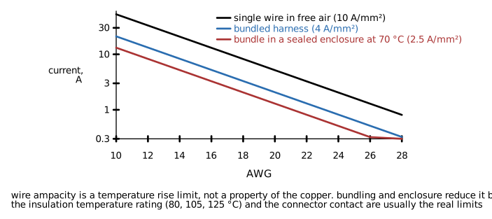 Figure 3. Wire current versus gauge for a single conductor in free air, a bundled harness, and a bundle in a warm sealed enclosure. The limit is insulation temperature, not copper.
Wire ampacity is a temperature limit on the insulation. The same copper carries three times more current alone in free air than in the middle of a bundle in a sealed box. Rules of thumb for hookup wire at a 105 °C insulation rating and moderate ambient: 10 A/mm² for a single wire in air, 4 A/mm² in a bundle, 2.5 A/mm² in a bundle in a warm enclosure. The AWG table and the cable voltage drop calculator on the tools page give the numbers per gauge; building and mains wiring follow their own codes.
Voltage drop
Copper resistance is 1.72 × 10⁻⁸ Ω·m at 20 °C and rises 0.39 % per °C. For a supply run the drop matters twice: it reduces the voltage at the load, and the return conductor doubles the loop resistance. A 3 A load through 5 m of 20 AWG (33 mΩ/m) round trip drops 1.0 V and wastes 3 W in the cable. Remote sense, a larger gauge, or a higher distribution voltage are the fixes.
Stranding and flex
Solid wire is for fixed installation and wire-wrap. Stranded wire is for anything that moves or is handled. Flex life rises with strand count: 7 strands for general hookup, 19 or more for flexing, 65 and up (fine-stranded, high-flex) for continuous-motion cables in cable carriers. Tinned strands resist corrosion and solder easily; bare copper is used where crimps must be uniform and cost matters.
Insulation
| Insulation | Temperature | Notes |
|---|---|---|
| PVC | 80 to 105 °C | Cheapest, general purpose, stiff at cold, not for high temperature |
| XLPE | 125 °C | Automotive, abrasion resistant |
| Silicone | 200 °C | Very flexible, soft, cuts easily |
| PTFE / FEP | 200 to 260 °C | Chemical resistance, thin wall, low loss for signals, expensive |
| Polyurethane (PUR) | 80 to 90 °C | Abrasion and oil resistant, cable jackets for machines |
| Irradiated PVC / ETFE | 105 to 150 °C | Thin wall, aerospace |
For cables, the jacket also sets flame rating (UL VW-1, CMR, CMP, LSZH for smoke and halogen), UV resistance, oil resistance, and the temperature range for flexing.
Termination
Crimp
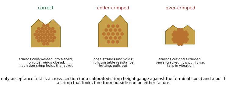 Figure 4. Cross-sections of a correct crimp, an under-crimped joint, and an over-crimped joint. Only a cross-section or a calibrated crimp height check can tell them apart.
A crimp deforms the terminal barrel around the wire strands until the strands cold-weld into a solid mass with no voids. Done correctly it is gas-tight, has lower and more stable resistance than a solder joint, survives vibration, and takes seconds. Done incorrectly it is the least reliable joint on the board.
The requirements:
- The terminal manufacturer's tool or a die with the same geometry. The crimp height and shape are specified per terminal and wire size, often to ±0.05 mm.
- The specified wire gauge range. A terminal for 20 to 22 AWG will not crimp 24 AWG correctly.
- Strip length matched to the barrel: strands visible past the barrel by about 0.5 to 1 mm, insulation held by the insulation crimp, no insulation in the conductor barrel.
- All strands in the barrel. A strand that escapes reduces the cross-section and can short to a neighbor.
- Qualification by crimp height measurement against the specification, a pull test to the terminal's rated force (typically 20 to 100 N for small terminals), and, for a new tool or wire, a cross-section (Figure 4). Pull tests alone do not detect over-crimping.
- Production control: pull-test samples per shift, tool calibration, and a specification that names the terminal, wire, and tool.
Hand tools with the correct dies are acceptable for prototypes and low volume. Pliers, ratchet tools with generic dies, and "universal" crimpers are not.
Solder
Soldering a wire to a terminal or pad is acceptable when the joint is strain-relieved so the wire cannot flex at the solder boundary. Solder wicks up the strands and produces a stiff section; the transition from stiff to flexible is a stress concentrator, and a soldered wire that flexes there breaks within tens of thousands of cycles. Solder joints also creep under sustained mechanical load, which is why solder is not a mechanical attachment.
Solder is the right choice for wires to a board that will be potted or strain-relieved, for cable-mount connectors with solder cups (with heat shrink over each joint and a strain-relieved backshell), and for rework. It is the wrong choice inside a crimp terminal, where it defeats the crimp's gas-tight interface and makes the joint brittle.
Insulation displacement (IDC)
IDC terminals cut through the insulation and grip the conductor. Ribbon cable connectors, some telecom and automotive terminals, and the wire-to-board "poke-in" families use it. It is fast and consistent with the correct tool and the specified cable; it is limited in current and gauge and does not tolerate wire substitution.
Press-fit
Press-fit pins deform into a plated hole and make a gas-tight joint without solder. Common for backplanes and automotive board-to-board. The hole diameter and plating are controlled dimensions, and the board must be supported during pressing.
Wire-to-board options
| Method | Typical current | Mating cycles | Notes |
|---|---|---|---|
| Crimp housing on a shrouded header (e.g. JST, Molex families) | 1 to 10 A per contact | 25 to 100 | The default for internal harnesses; keyed and latched variants |
| Screw terminal block | 5 to 30 A | Unlimited | Field wiring; torque specification |
| Spring-cage terminal block | 5 to 30 A | Unlimited | Vibration tolerant, no torque |
| Poke-in / IDC wire-to-board | 1 to 5 A | 1 to a few | Fast assembly, no field service |
| Direct solder with strain relief | Any | 0 | Prototypes, potted assemblies |
| Faston / blade | 10 to 30 A | Tens | Power, appliance |
Connector families by use
| Application | Typical choice | What matters |
|---|---|---|
| Internal signal harness, 2 to 20 pins | 1.0 to 2.5 mm pitch crimp housings with a latch | Latch, keying, crimp tooling in house |
| Internal power | 3 to 4.2 mm pitch power housings, blade terminals | Current derating, contact plating, wire gauge |
| Board-to-board, mezzanine | Fine-pitch stacking connectors | Stack height tolerance, mating cycles, alignment |
| Board-to-board, edge | Card-edge connectors, gold fingers | Finger plating thickness, insertion count |
| Ribbon cable | IDC to 1.27 or 2.54 mm headers | Cable spec, keying, EMI (ribbon is unshielded) |
| Panel, external, general | D-sub, circular (M12, M8), USB, RJ45 | Sealing, mating cycles, shield continuity, standards compliance |
| Automotive and harsh | Sealed automotive families, MIL-DTL-38999 style circular | Sealing, vibration, temperature, defined tooling |
| High current | Power pole style, ring terminals on studs | Contact force, torque, insulation |
| Debug and programming | Fine-pitch headers, pogo-pin fixtures | Cycle count on a programming header is the limit |
The features that separate a reliable choice from a cheap one at the same pitch: a positive latch, polarization or keying, a housing that captures the contacts against vibration, a specified normal force and plating, published derating curves, and a defined crimp tool.
Shielded cables and termination
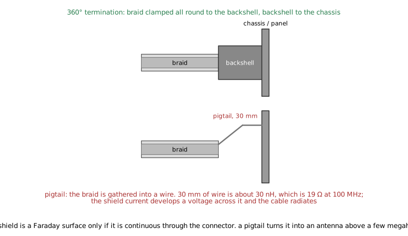 Figure 5. Shield termination. A 360° clamp keeps the shield continuous through the connector; a pigtail turns the last few centimeters into an inductor.
A cable shield works by carrying the noise current on its outer surface so that the inner conductors see none of it. That requires the shield to be a continuous conductive surface from one enclosure to the other, including through the connector. The shield's effectiveness is limited by its transfer impedance, the voltage that appears inside per unit of current on the outside, per unit length. A good braid has a transfer impedance of a few milliohms per meter at low frequency, rising above 1 MHz as the braid's holes let field through; foil with a drain wire is worse at low frequency and fine at high; a combination of foil and braid is the general-purpose choice.
The termination is the weak point:
- 360° termination. The braid is clamped or soldered around its full circumference to a conductive backshell, which contacts the connector shell, which contacts the chassis. The transfer impedance at the joint is milliohms. This is the only termination that preserves the shield at frequencies above a few megahertz.
- Pigtail. The braid is gathered into a wire and connected to a pin or a ground point. A 30 mm pigtail is about 30 nH, which is 19 Ω at 100 MHz; the shield current develops a voltage across it, and that voltage drives the cable as an antenna. Pigtails degrade shielding by 20 to 40 dB above 10 MHz. They are acceptable only for audio-frequency shielding.
- Grounded at one end or both. For frequencies above about 100 kHz the shield must be grounded at both ends to carry the current that cancels the field. Single-ended grounding is an audio-frequency practice to avoid ground loops at 50 or 60 Hz; the modern solution to that problem is both ends grounded with a hybrid (a capacitor to chassis at one end) or with isolation in the signal path.
- Shield to signal ground versus chassis. The shield is part of the enclosure and connects to chassis at the point of entry. Connecting it to the circuit ground inside routes the shield's noise current across the board.
Connector shells for shielded cables (D-sub with metal backshell, M12 with shielded variants, RJ45 with a shielded jack, USB) are designed for the 360° connection; the design must give them a path to chassis with low inductance, usually a panel mount or a set of chassis-ground vias at the connector footprint.
Mechanical and environmental
Locking and retention
Every connector that can vibrate loose or be pulled needs positive retention: a latch, a screw lock, a bayonet, or a friction fit rated for the environment. Unlocked friction-fit headers (bare pin headers with a crimp housing) are for benches and prototypes.
Strain relief
The cable must be held so that no load reaches the terminations. Options: a molded strain relief, a cable clamp in the backshell, a cable tie to a nearby anchor, a service loop. The strain relief takes the pull, the bend, and the vibration; the crimp or solder only conducts.
Mating cycles
Rated cycles range from 1 to 10 (IDC, poke-in) through 25 to 100 (crimp housings, board-to-board) to 500 to 10000 (USB, D-sub, circular connectors with thick gold). A product that will be serviced, reprogrammed, or reconfigured needs a connector rated for its life, and a debug header on a production line needs a fixture, not repeated mating.
Sealing
IP ratings describe the mated connector, and usually require the specified cable diameter in the seal, the specified torque on the gland or coupling nut, and a cap on the unmated connector. A sealed connector that is not sealed at the cable entry is not sealed. Breathable membranes on enclosures avoid pumping moisture through connector seals with temperature cycling.
Temperature and vibration
The housing material sets the temperature range (nylon 105 °C, PBT and LCP 125 to 150 °C); the contact spring's relaxation sets it for force retention over life. Vibration qualifications (random vibration profiles per automotive or industrial standards) are published for automotive and industrial families and absent for commodity parts; a commodity connector in a vibrating product is a fretting failure waiting to happen.
Failure modes
| Failure | Mechanism | Symptom | Prevention |
|---|---|---|---|
| Fretting corrosion | Micro-motion oxidizes tin at the interface | Intermittent, resistance rises over months, worse with thermal cycling | Locked housings, gold, lubricant, adequate force |
| Crimp failure | Under- or over-crimp, wrong wire, wrong tool | High resistance, heating, pull-out | Correct tooling, height and pull qualification |
| Wire fatigue at a solder joint | Flex at the stiff transition | Open circuit after handling or vibration | Crimp instead, or strain relief |
| Contact overheating | Current above the derated rating, aged contact resistance | Discolored housing, melted plastic, fire | Derate, inspect, use power contacts |
| Backed-out contact | Contact not latched in the housing | Open or intermittent, contact pushed back on mating | Retention check (push test) at assembly, correct insertion |
| Bent pin on mating | Misalignment, no guide | Open or short | Keying, guide pins, shrouded headers |
| Corrosion | Moisture, salt, sulfur, dissimilar metals | Rising resistance, green or black deposits | Sealing, plating, conformal coating away from contacts |
| Shield ineffective | Pigtail, unconnected shell | Emissions failure, susceptibility | 360° termination to chassis |
| Wrong mating | No keying | Reversed power, damaged parts | Keyed housings, distinct connectors per function |
Design procedure
- List each connection: signals, currents, voltages, cycle count, environment (temperature, vibration, moisture, chemicals), and whether it is factory-only or field-serviced.
- Choose the family by application from the table, preferring one with published derating curves, defined crimp tooling, and multiple sources for the housing and contacts.
- Derate the current for ambient, loaded positions, and enclosure; confirm the wire gauge is within the terminal's range and meets the ampacity and voltage drop.
- Confirm creepage and clearance for the voltage and environment, and leave positions empty if needed.
- Specify the termination method and the tool; for crimps, the terminal part number, wire, tool, crimp height, and pull force go into the assembly drawing.
- Specify strain relief, retention, keying, and sealing on the drawing.
- For shielded cables, specify the termination (360° to a shell that reaches chassis) and design the board's chassis-ground connection at the connector.
- Mark polarity and pin 1 on the silkscreen and the housing; make different functions non-intermateable.
- Qualify the assembly: crimp cross-section and pull test at first article, contact retention, mating force, and a thermal test at the derated current with all positions loaded.
Design errors
- Rating read as continuous with all pins loaded. Correction: derate per the curves; plan on 50 to 60 %.
- Tin contacts in a vibrating product with an unlatched housing. Correction: latch, gold, or lubricant.
- Crimp terminals soldered "for reliability". Correction: crimp only; the solder destroys the crimp.
- Generic crimp tool. Correction: manufacturer's tool or die, with height and pull qualification.
- Shield pigtailed to a signal ground pin. Correction: 360° to the shell, shell to chassis.
- Unsealed cable entry on an IP-rated connector. Correction: correct cable diameter in the seal, torque, caps.
- Debug header used for production programming. Correction: a pogo-pin fixture; the header's cycle rating is for debugging.
- Paralleled contacts rated at the sum of their ratings. Correction: derate the total by 20 to 30 % for imbalance.
- Dry-circuit signal on tin. Correction: gold, or a wetting current.
- No strain relief on a cable to a board. Correction: clamp, tie, or molded relief that takes all mechanical load.
Limitations of this document
- Derating curves, contact resistance values, and cycle ratings are typical ranges across families. The manufacturer's data for the specific series governs.
- Wire ampacity figures are rules of thumb for hookup wire; building, mains, and vehicle wiring follow their own standards and codes.
- Safety spacing and rated voltage follow the product standard; see the creepage and clearance calculator and IEC 60664-1.
- RF connector performance (VSWR, insertion loss above 1 GHz), fiber optics, and high-speed differential connector signal integrity are outside the scope.