Debug and Bring-Up
noteA procedure for the first power-on of a new board and for finding faults afterward: inspection before power, the current-limited supply and what its reading means, the order in which rails, clocks, reset, and the debugger are checked before any firmware runs, a fault-finding order by prior probability, bisection of a signal chain, the instruments and how to use them without lying to yourself, the failure patterns that account for most new-board problems, and how to record what was found.
Scope: the first power-on of a newly assembled board and the diagnosis of a board that does not work, whether new or returned from the field. The note gives an order of operations, a stop rule for each stage, the fault-finding method that finds most problems fastest, the measurements that distinguish the common failures, and the record-keeping that makes the second board faster than the first. Firmware debugging (breakpoints, logging, protocol analysis) is covered only where it interacts with the hardware.
Common errors
- Plugging the board into the final supply. The first power-on goes through a bench supply with the current limit set to slightly above the expected quiescent current. A solder bridge on a 5 A supply is a burned trace; on a 50 mA limit it is a reading.
- Loading firmware before the hardware has passed. A processor that resets, a rail that sags under load, a clock that starts late: each looks like a firmware bug from the debugger's side, and the debugger's side is where the first day gets spent.
- Trusting the schematic over the board. The board is the artifact. A net that the schematic says is connected may not be; a part the BOM says is 10 kΩ may be 10 Ω.
- Changing two things at once. Two changes and a fixed board tell nothing about which change fixed it, and one of them may have been harmful.
- Measuring with a bad ground. A scope probe with a 15 cm ground lead shows ringing that is not on the board and hides noise that is. Every measurement that matters is made with a short ground at the point of measurement.
- Assuming the instrument. A DMM on a switching node reads an average; a scope with a 20 MHz bandwidth limit on hides the 50 MHz ring; a logic analyzer shows a threshold-crossing, not a voltage.
- Not writing it down. The fault found on Tuesday is the fault of the next revision and of the field unit that comes back in a year.
Before power
- Visual inspection under magnification: solder bridges (especially fine-pitch ICs and under the edges of QFNs), missing or tombstoned parts, parts rotated (polarized capacitors, diodes, ICs with the pin 1 mark), wrong parts (a 0402 in the wrong place, a part with a marking that does not match the BOM), and solder balls.
- Ohmmeter on every rail to ground, power off. A dead short on a rail is found here, not with the supply. Note the reading; a low but non-zero resistance (tens of ohms) on a rail with a large IC may be normal (internal pull-downs, protection structures) and the reading compared with a known-good board settles it. A diode-test reading of 0.3 to 0.7 V in one polarity is the IC's substrate diode and normal.
- Ohmmeter between rails that should be isolated, and from rails to any exposed metal.
- Check the input: polarity of the connector, the fuse, and that the supply's voltage matches the board's rating.
- Set up the bench supply: voltage at nominal, current limit at about twice the expected quiescent current for the first stage (typically 20 to 100 mA for a board with a microcontroller and a few regulators). Note what the expected current is; an estimate from the datasheets is enough.
First power-on
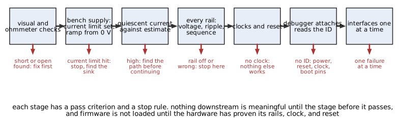 Figure 1. The first power-on sequence. Each stage has a pass criterion and a stop rule; nothing downstream is meaningful until the stage before it passes.
Ramp and current
Apply the supply and watch the current. Ramping the voltage from zero (a supply with a slow ramp, or a manual turn of the knob) shows at what voltage the current jumps, which identifies a shorted regulator or a latched-up part. The supply hitting its current limit is a stop: find the sink before proceeding. A thermal camera or a finger (carefully, on the low-voltage side) finds the hot part in seconds; a shorted regulator output or a reversed tantalum is warm within a few seconds at 100 mA.
If the current settles at roughly the expected value, raise the limit to the expected full-load value plus margin and continue.
Rails
Measure every rail with a DMM at the rail's capacitor, not at the regulator's pin: voltage within tolerance, and the same on every part of the board that the rail reaches. Then with a scope: ripple and noise (AC coupled, bandwidth appropriate to the regulator's switching frequency), and the sequence and ramp of each rail from power-up if the design has sequencing requirements (many processors require the core rail before or after the I/O rail within a window). A rail that is low by a regulator's dropout, or that is present but with 200 mV of switching ripple, or that comes up before its enable, is found here.
Any rail wrong is a stop. The failures downstream of a bad rail are not diagnosable until the rail is right.
Clocks and reset
With a scope (a low-capacitance probe on any crystal, or the clock output pin), confirm every oscillator runs at its frequency. Confirm the reset line: released after the rails are stable, at the right level, not glitching, and not held by a supervisor whose threshold is above the rail. A processor with no clock or a held reset does nothing, and looks identical to a dead one.
The debugger
Attach the debugger and read the device ID. This is the first moment the processor talks. Success means the rails, clock, reset, and the debug interface all work; failure means one of them does not, and the list of suspects is short: the debug interface's own pins (pull-ups, a boot-mode pin, a swapped pair), the clock, the reset, or the rails at the processor's pins.
Do not load firmware yet. Read and write a peripheral register through the debugger (an on-chip RAM location, a GPIO register) to prove the bus.
Firmware, one interface at a time
The first firmware toggles a GPIO and nothing else. Then it turns on the crystal oscillator and proves the frequency at a pin. Then a UART with a loopback, then the debug console, then each interface with its own hardware test: an I2C address scan, an SPI register read of a device ID, an ADC reading of a known voltage, a PWM measured on a scope. Each interface has a note in this collection with its bring-up checks. One failure at a time, in an order that lets each layer stand on the last.
The fault-finding order
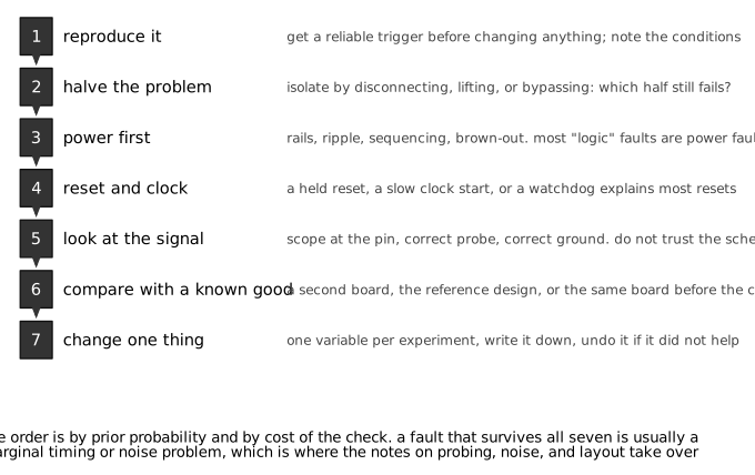 Figure 2. A fault-finding order by prior probability and cost of the check. Most faults are found in the first four steps.
For a board that worked and now does not, or a board that passes bring-up but fails in operation:
- Reproduce it. A fault that cannot be triggered cannot be found. Determine the conditions: which operation, what temperature, which unit, which cable, after how long. If it is intermittent, find the thing that changes its rate (heat, cold spray, flexing the board, tapping, supply voltage at the margin, load). Change nothing until the trigger is reliable.
- Halve the problem. Disconnect, lift, or bypass to find which half still fails: the power section or the load; the board or the cable; this unit or all units; this firmware version or the last. Each halving eliminates half the suspects for the cost of one test.
- Power first. Most faults reported as logic, timing, or software faults are power faults: a rail that sags on a load step, ripple at a frequency that beats with something, a brown-out detector tripping, a regulator in dropout at the high end of the temperature range, a ground bounce from a shared return. Scope the rails at the failing part during the failure.
- Reset and clock. A reset that glitches, a watchdog that fires, a supervisor with a marginal threshold, an oscillator that stops when something else switches, a PLL that loses lock. The reset line on a scope, triggered on its falling edge, catches most of these.
- Look at the signal. At the pin, with the right probe and a short ground. The schematic says what the signal should be; the scope says what it is. Levels, edges, timing, and noise.
- Compare with a known good. A second unit, the reference design, the same board before the change, the same measurement on a working channel. The difference is the fault.
- Change one thing. A component, a firmware setting, a cable, a supply. Record it, observe, and undo it if it did not help. A change that helps is a clue, not necessarily the cause: a capacitor added at a pin that fixes a reset problem is evidence of a noise coupling path, and the path is the fault.
Bisection
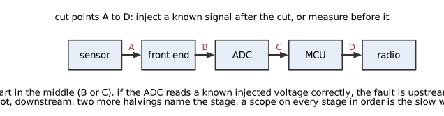 Figure 3. Bisecting a signal chain. Inject a known signal after a cut point, or measure before it, starting in the middle.
A signal chain (sensor, amplifier, filter, ADC, processor, output) with a wrong result at the end is bisected: inject a known signal at the middle, or measure the middle, and determine which half is wrong. Two more steps name the stage. The tools: a signal generator or a precision voltage for injection, a scope or DMM for measurement, and a way to read the digital value (the debugger, a debug print). Working from the input forward, stage by stage, is the slow method.
Instruments and their traps
| Instrument | Good for | Trap |
|---|---|---|
| Bench supply with current limit | First power-on, finding shorts, measuring quiescent current | The current reading is an average; a pulsed load reads low |
| DMM | Rail voltages, resistances, diode checks, continuity | Averages everything; 1 kHz bandwidth at best; the continuity beeper has a threshold of tens of ohms |
| Oscilloscope with passive probe | Everything dynamic | The ground lead (use the spring tip), probe loading on high-impedance nodes, bandwidth limits, and the probe's ground being the board's ground (never on a floating node without a differential probe) |
| Scope with current probe | Supply current waveforms, converter currents | Insertion inductance, DC offset drift |
| Logic analyzer | Protocol decoding, timing between many signals | Shows only threshold crossings; the analog problem is invisible |
| Thermal camera | Finding the hot part in seconds | Emissivity of shiny surfaces; a part can be hot and fine |
| Cold spray and heat gun | Localizing temperature-dependent faults | Condensation from cold spray adds leakage; the heat gun can damage parts |
| Bus analyzer (CAN, USB, I2C) | Protocol errors and their source | Reports the symptom, not the electrical cause |
| Frequency counter | Crystal accuracy | Probe capacitance pulls the crystal; use a divided output |
The oscilloscope probing note covers the measurements that are most often wrong. The rule for bring-up: when a measurement looks strange, the measurement is the first suspect.
Common failure patterns
| Symptom | Likely cause | Check |
|---|---|---|
| Supply hits current limit at power-on | Solder bridge, reversed polarized part, shorted regulator, part inserted backward | Ohmmeter before power; thermal camera; ramp the voltage |
| Current normal, no activity | No clock, held reset, wrong boot-mode pins, debug interface miswired | Scope the crystal and reset; read the device ID |
| Works then resets under load | Rail sag, brown-out, watchdog, ground bounce into reset | Scope the rail and reset at the load step |
| Works cold, fails warm (or vice versa) | Marginal timing, a component at its temperature limit, a leakage path, a regulator in dropout | Heat gun and cold spray on sections, then parts |
| Works on the bench, fails in the enclosure | Thermal, EMI from a neighbor, a cable that is longer, a connector under strain | Reproduce with the enclosure; measure temperature |
| One unit fails, others pass | Assembly defect, a part at the edge of tolerance, a cracked ceramic, a cold joint | Swap parts between units; X-ray or cross-section the suspect |
| All units fail the same way | Design fault, wrong part in the BOM, firmware | Compare with the schematic and the reference design; check part markings |
| Intermittent, changes with tapping or flexing | Cracked solder joint, cracked MLCC, connector contact, hairline trace crack | Flex and tap while monitoring; reflow the suspect area |
| Analog reading offset or drifting | Ground loop, thermocouple effects at connectors, leakage from flux, a bias current into a high impedance | Measure with the input shorted; clean the board; check the ground path |
| Interface works at short range, fails at long | Signal integrity, pull-up sizing, missing termination, ground potential difference | The interface note's bring-up checks |
| Random data corruption | Noise on a clock, a marginal level, setup or hold violation, a supply glitch | Scope the clock and data at the receiver, at the failing moment |
| Regulator output oscillates | Wrong output capacitor type or value, input inductance with no input capacitor | Scope the output; the regulator note's stability section |
Recording
For each fault, the record holds: the symptom and how to reproduce it; the measurements that localized it, with the instrument and setup; the cause; the fix; and what changes in the design, the assembly process, or the test procedure follow from it. The record is what turns a bring-up into a checklist for the next unit and a design review item for the next revision. The minimum is a dated log with photographs of scope traces; a defect tracking system is better once there is more than one board or one person.
The end of a bring-up is a test procedure: the sequence of measurements, with pass limits, that a technician can run on the next unit without the designer present. It is the first draft of the production test.
Design for bring-up
The board itself can make this easier:
- Test points on every rail, on reset, on every clock, and on the debug interface, with a ground point within a probe's spring-tip reach of each.
- A current-sense jumper or 0 Ω resistor in each rail so the current can be measured and a section isolated.
- Rails that can be powered separately, or 0 Ω links between sections, for halving the problem.
- Unpopulated series resistors on bus lines where a lifted part or an isolation may be needed.
- LEDs or a status output on the processor that need nothing but the core to work.
- A debug console that comes up in the first firmware.
- Silkscreen that names rails, test points, and connectors, and marks pin 1 and polarity.
Design errors
- First power from the final supply. Correction: bench supply, current limit, voltage ramp.
- Firmware loaded before rails, clock, and reset are proven. Correction: the stage order; device ID before any code.
- Rails measured at the regulator, not at the load. Correction: DMM and scope at the load's capacitor.
- Ripple measured with a long ground lead. Correction: spring tip, or a coax probe.
- Fault "fixed" by adding a capacitor with no explanation. Correction: find the coupling path the capacitor is masking.
- Two changes at once. Correction: one at a time, recorded, undone if ineffective.
- Intermittent fault chased without a reliable trigger. Correction: find what changes the rate first.
- Cold spray on an analog board without cleaning. Correction: expect condensation leakage; dry and re-test.
- No test points, no current jumpers. Correction: add them in the first revision.
- Nothing written down. Correction: a log with traces; a test procedure at the end.
Limitations of this document
- The order and the failure table are drawn from typical microcontroller-based boards with switching and linear regulators; RF, high-voltage, and high-power boards add hazards and steps (in particular, high-voltage bring-up needs isolation, interlocks, and a procedure before the first power-on).
- The instrument traps are summarized; the probing note gives the detail.
- Firmware-side debugging, production test design, and failure analysis (cross-sections, decapsulation) are outside the scope.