Inductors and Magnetics
noteHow to read an inductor datasheet and pick a part that works in a switching converter: the equivalent circuit, saturation versus thermal current ratings and why they are independent, ferrite versus powder cores, core loss from ripple, DCR and AC resistance, self-resonance, shielding and EMI, coupled inductors, transformers and leakage, a selection procedure, and a worked example.
related tools: reactance and lc resonance, inductor sizing (buck converter), inductor sizing (boost converter), flyback converter stresses, rcd clamp (flyback)
Scope: inductors and small transformers as used in switching converters, filters, and signal paths from a few kilohertz to a few megahertz. The note covers the parameters on a datasheet, what each one means in the circuit, the two current ratings and the mechanisms behind them, core materials, losses, coupled parts, and selection. Custom magnetics design (turns, core sizing, winding layout) is described only far enough to read a vendor's part; RF inductors above 30 MHz and power-line chokes are outside the scope.
Common errors
- Reading one current rating. An inductor has two: the saturation current, set by the core, and the RMS or heating current, set by the winding. They are independent, and a part can pass one and fail the other.
- Checking saturation against the average current. Saturation is a peak phenomenon. The inductor must hold its inductance at the peak of the ripple, at the peak of the load step, and at startup and short-circuit current if the controller allows them.
- Assuming the datasheet inductance. A ferrite part near its saturation rating and a powder part at any significant current both have less inductance than marked. The ripple current, the peak current, and the control loop all depend on the value at the operating point.
- Ignoring core loss. DCR describes the loss at DC. At high ripple the core loss can exceed the copper loss, and the datasheet's thermal rating does not include it.
- Treating an inductor as an inductor above its self-resonance. Above the SRF the winding capacitance dominates and the part is a capacitor. A 100 µH filter inductor may be useless above 5 MHz.
- Choosing a small unshielded part for a switching converter and then adding filters for the noise. The flux from an open-core inductor couples into adjacent traces and parts; the fix is a shielded part in the first place.
- Sizing a flyback or coupled inductor by inductance alone. Leakage inductance, winding polarity, and isolation rating decide whether the circuit works.
What an inductor actually is
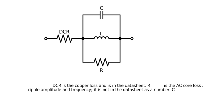 Figure 1. Equivalent circuit of an inductor. DCR is the copper loss; the core loss resistance depends on ripple and frequency and is not a datasheet number; the parallel capacitance sets the self-resonant frequency.
An inductor is a winding on a core. The inductance is set by the turns, the core material, and the core geometry:
where Ae is the effective core area, le the effective magnetic path length, and AL the core's inductance factor in nH per turn squared. The equation contains the mechanism of every rating: µr depends on the flux density, which depends on the current, so the inductance is a function of current; the winding has resistance, which sets the copper loss; the core has loss that depends on the AC flux swing; and the turns have capacitance to each other, which sets the self-resonant frequency.
Datasheet parameters
| Parameter | What it is | What sets it | What it decides |
|---|---|---|---|
| L (nominal) | Inductance at zero current, at a stated test frequency, typically 100 kHz or 1 MHz | Turns, core | Ripple current, filter corner |
| Tolerance | Usually ±20 %, ±30 % for powder cores | Manufacturing | Worst-case ripple and control loop |
| Isat | DC current at which L has dropped by a stated fraction (10, 20, or 30 %) | Core material and area | Peak current the part can carry |
| Irms (Iheat, Itemp) | DC current for a stated temperature rise (20 or 40 °C) on the vendor's test board | Winding resistance, package surface | Continuous current |
| DCR | Winding resistance at 20 °C, with a maximum | Wire gauge and length | Copper loss, efficiency, and it rises 0.4 % per °C |
| SRF | Frequency where L resonates with the winding capacitance | Turns, winding geometry | Upper useful frequency |
| Q | Ratio of reactance to total loss at a test frequency | Core and copper loss | Filter selectivity, loss at that frequency |
| Rated voltage | For some parts, the maximum working voltage across the winding | Insulation | Relevant to coupled and high-voltage parts |
| Shielding | Open, semi-shielded, or shielded (closed magnetic path) | Construction | Radiated field, coupling to neighbors |
| Operating temperature | Includes self-heating | Core and insulation limits, typically 125 °C total | Ambient plus rise budget |
The nominal inductance is specified at a small signal and zero current. Neither describes a converter, where the inductor carries a DC current with a ripple of tens of percent.
The two current ratings
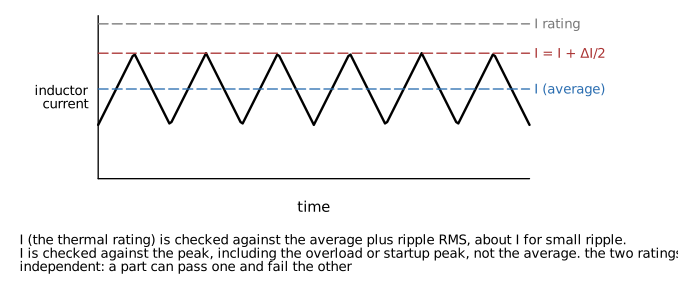 Figure 2. Inductor current in a converter, and which rating applies where. The RMS rating is checked against the average; the saturation rating against the peak.
Saturation current
Flux density in the core rises with current. Above a material-dependent flux density the core cannot magnetize further, the permeability falls toward that of air, and the inductance collapses. The datasheet Isat is the DC current at which the inductance has dropped by a stated amount, and the amount varies by vendor: 10 %, 20 %, and 30 % are all used, so two parts with the same Isat number can differ by a factor of 1.5 in the current at which they actually saturate.
Saturation is a peak quantity. The relevant current is the highest instantaneous current the inductor sees:
plus whatever the controller allows during a load step, at startup (the soft-start current limit), and in a fault (the current limit or the short-circuit current). A converter whose inductor saturates at the current limit has no current limit: the inductance collapses, di/dt rises, and the peak current runs away within one switching cycle, typically faster than the controller's current sense can respond.
Saturation current falls with temperature for ferrite cores, by 20 to 30 % between 25 °C and 100 °C, and the datasheet value is at 25 °C.
RMS or heating current
Copper loss is I²R in the winding, plus core loss, and the part's temperature rise follows from the total loss and the thermal path to the board. The datasheet Irms is the DC current that produces a stated rise (typically 40 °C) on the vendor's test board in still air. It is a thermal rating and depends on the mounting: a part on a small board with no copper pour runs hotter than the rating, and a part next to a hot MOSFET starts from a higher ambient.
For a converter, the RMS current is
which is within a few percent of the DC value for ripple below 40 %. The check is Irms against the rating, derated for the actual board and the actual ambient, with the core loss added.
Why they are independent
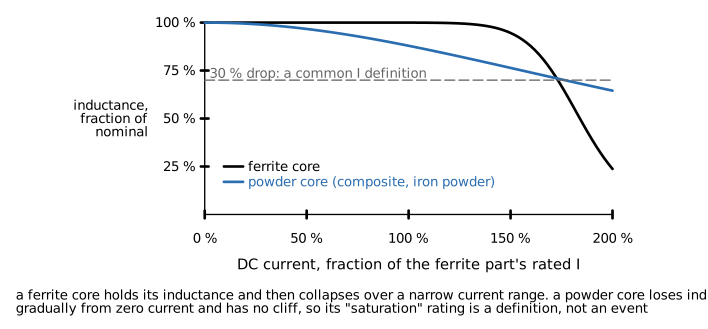 Figure 3. Inductance versus DC current for a ferrite core and a powder core. The ferrite holds and then collapses; the powder core rolls off gradually with no cliff.
Saturation depends on the core (material and cross-section). Heating depends on the winding (wire gauge and length) and the surface area. A part with a large core and thin wire has high Isat and low Irms; a part with a small core and heavy wire has the reverse. Small, low-profile parts with high inductance per volume are often saturation-limited; large parts with few turns are often thermally limited. Both ratings must be checked against their own current.
Core materials
| Material | Permeability | Saturation behavior | Core loss | Cost | Typical use |
|---|---|---|---|---|---|
| Ferrite (MnZn) | 1000 to 10000 | Hard: flat then collapses near Bsat (0.3 to 0.5 T) | Low | Low | Power inductors to a few megahertz, transformers |
| Ferrite (NiZn) | 20 to 1000 | Hard | Low at high frequency | Low | Above 1 MHz, EMI, beads |
| Iron powder | 10 to 100 (distributed gap) | Soft: gradual roll-off from zero | High | Lowest | Low-frequency chokes, DC-heavy filters, older designs |
| Sendust, MPP, High Flux (alloy powder) | 26 to 160 | Soft | Moderate to low | Medium to high | Chokes with DC bias, PFC |
| Composite (molded metal powder) | 20 to 60 | Soft | Moderate | Medium | Modern molded power inductors |
| Air (no core) | 1 | None | None | - | RF, high-current low-inductance |
Ferrite parts hold their inductance up to the saturation current and then lose it over a narrow range (Figure 3). They have low core loss, so they run cool at high ripple, and high permeability, so they need few turns and have low DCR for the inductance. The cliff is the hazard: a ferrite part at 90 % of its saturation rating is fine, and at 130 % it is a short circuit.
Powder cores have a distributed air gap in the binder between metal particles. Inductance falls gradually from zero current (a "soft saturation" curve), typically to 70 % of nominal at the rated current and 50 % at twice the rating, with no cliff. Composite molded parts are the current default for point-of-load converters because they tolerate transient peaks, are mechanically robust (the winding is molded into the core, so there is no wire to move or crack), and are self-shielded. The costs are higher core loss than ferrite at the same ripple, a lower nominal inductance per volume, and an inductance that must be read from the curve at the operating current.
Gapped ferrite (a ferrite core with a deliberate air gap) sits between: the gap stores the energy, raises the saturation current, and makes the inductance less sensitive to permeability, at the cost of fringing flux around the gap that heats nearby copper and radiates. Most drum-core and E-core power inductors are gapped ferrite.
The material also sets the temperature range. Ferrite's permeability and saturation flux both drop as the Curie temperature approaches (150 to 250 °C for power ferrites), and a part rated to 125 °C loses margin above 100 °C. Powder cores hold their properties to higher temperatures but their binder ages with time at temperature, which limits some composite parts to 125 °C or less for life.
Losses
Copper loss
DC copper loss is I²·DCR, with DCR rising 0.39 % per °C for copper: a winding at 100 °C has 30 % more resistance than at 20 °C, which is the temperature at which the datasheet DCR is specified. At switching frequencies the ripple current also sees AC resistance from skin and proximity effects. Skin depth in copper is
which is 0.21 mm at 100 kHz and 0.066 mm at 1 MHz. Wire thicker than twice the skin depth carries ripple current only in its outer layer, and multilayer windings suffer proximity effect that raises the AC resistance by a further factor of several. For a converter at moderate ripple the AC copper loss is a small correction; for a resonant converter or a high-ripple design it can dominate, and the vendor's AC resistance curve or a loss calculator is needed.
Core loss
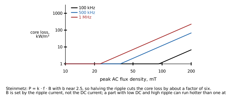 Figure 4. Core loss density versus peak AC flux density for a power ferrite at three frequencies. The loss goes roughly as the 2.5 power of the flux swing.
The core dissipates energy each cycle as the flux swings. The Steinmetz equation describes it:
with a near 1.3 to 1.7 and b near 2 to 2.7 for power ferrites, and Pv in kW/m³ or mW/cm³. The flux swing comes from the ripple current, not the DC current:
The consequence is that core loss depends strongly on ripple and hardly at all on load. A converter at light load with the same ripple has the same core loss as at full load, and a design with 60 % ripple has about five times the core loss of one with 30 %. Vendors publish core loss either as a curve against ripple current at frequency, or through an online calculator that takes the operating point and returns copper and core loss separately. Those calculators are the only practical way to get the number for a specific part.
Temperature rise
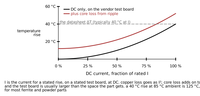 Figure 5. Temperature rise versus DC current, on the vendor's test board, with and without the core loss from ripple.
Total loss is copper plus core, and the rise is that loss times the thermal resistance of the part on its board. Datasheet Irms includes copper loss only, on a board that is usually larger than the space the part gets. The design check is
with Rth estimated from the datasheet (the rated rise divided by I²rms·DCR at the rated current) and corrected for the real board. The result must stay below the part's maximum operating temperature, which for most power inductors is 125 °C including self-heating, and the Isat check must be repeated at that temperature for a ferrite part.
Self-resonance and high frequency
The turns have capacitance to each other and to the core. That capacitance resonates with the inductance at the SRF, above which the part is capacitive. For a power inductor the SRF is typically 10 to 100 MHz and is not a design constraint in a converter switching below 2 MHz, but it matters in two places:
- A filter inductor is a filter only below its SRF. A 100 µH choke with an SRF of 3 MHz does nothing for conducted emissions at 30 MHz, and the impedance at the SRF itself is a peak that can worsen a resonance with the filter capacitor.
- A high-Q inductor rings with parasitic capacitance at the switch node, which is a source of the switch-node ringing that snubbers address.
Above the SRF, common-mode chokes and ferrite beads use the winding's loss deliberately; see the ferrite bead note.
Shielding and EMI
An inductor stores energy in a magnetic field, and the field of an open-core (drum, rod, or unshielded bobbin) part extends outside the package. Consequences:
- The field couples into nearby traces, into other inductors (two unshielded parts side by side are a transformer), into sense resistors, and into sensitive analog nodes, at the switching frequency and its harmonics.
- The field induces eddy currents in nearby copper planes, which adds loss and reduces the inductance.
- The part radiates, which shows up in emissions testing.
Shielded parts close the magnetic path with a ferrite shell or a molded body, which contains the field to a few millimeters. Semi-shielded parts add a magnetic epoxy skirt to a drum core. For a switching converter the shielded part is the default; the unshielded one is used only where cost or height rules and the layout keeps sensitive circuits away from it.
Orientation also matters for coupled fields: two adjacent open-core inductors with parallel axes couple strongly, and rotating one by 90° reduces the coupling substantially.
Coupled inductors and transformers
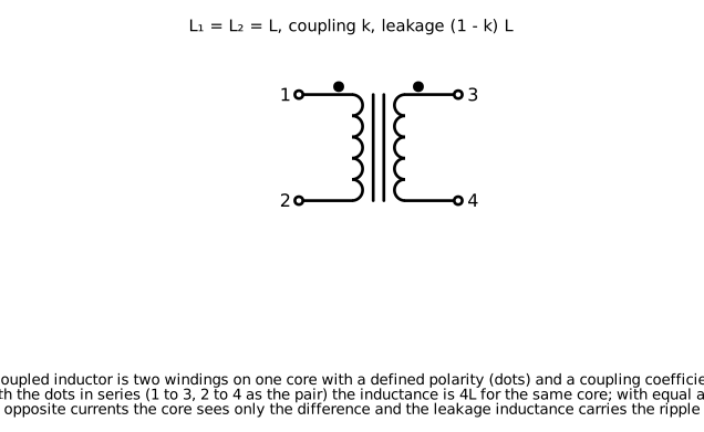 Figure 6. A coupled inductor: two windings on one core with a defined polarity and a coupling coefficient. Leakage inductance is the part of each winding's flux that does not link the other.
A coupled inductor is two or more windings on one core. The mutual inductance is M = k·√(L1·L2), where k is the coupling coefficient (0.9 to 0.99 for parts designed to couple), and the leakage inductance of each winding is roughly (1 - k)·L. Polarity is marked with dots: current entering both dotted ends produces flux in the same direction.
Uses:
- SEPIC, Zeta, and Ćuk converters use a coupled inductor to replace two separate ones, saving space and, with the right leakage, reducing ripple in one winding at the expense of the other.
- Multi-phase buck converters use inverse-coupled inductors to cancel DC flux and reduce the ripple in each phase.
- Flyback transformers are coupled inductors used as energy storage: the primary stores energy in the gap during the on-time and the secondary delivers it during the off-time. The turns ratio sets the reflected voltage and the leakage inductance sets the switch voltage spike that the clamp must absorb.
- Common-mode chokes are coupled inductors wound so that differential current cancels and common-mode current sees the full inductance.
- Isolated transformers for forward, push-pull, half- and full-bridge converters transfer energy directly rather than storing it, and are designed for minimum leakage and minimum magnetizing current rather than for energy storage.
Parameters specific to coupled parts:
| Parameter | Meaning | Why it matters |
|---|---|---|
| Turns ratio N | Primary to secondary turns | Reflected voltage, output voltage, stresses |
| Leakage inductance | Flux not linking the other winding | Switch voltage spike, clamp loss, cross-regulation |
| Magnetizing inductance | Inductance seen at the primary with the secondary open | Magnetizing current, flyback energy storage |
| Isolation voltage | Test voltage between windings, and the insulation class (functional, basic, reinforced) | Safety, creepage and clearance |
| Interwinding capacitance | Capacitance between windings | Common-mode noise coupling across the isolation barrier |
| Volt-second rating | Maximum V × t per half cycle before saturation | Sets the minimum frequency or maximum duty |
An off-the-shelf flyback transformer is specified for a controller and an operating point. Using it elsewhere requires checking the volt-seconds at the new voltage and frequency, the magnetizing inductance against the desired CCM/DCM boundary, and the peak current against saturation.
Reading the datasheet
- L versus I curve, at the operating temperature if given. Read the inductance at the peak current, not the average, and design the ripple with that value.
- Isat definition. Find the percentage drop it corresponds to, and compare across vendors on the curve rather than the number.
- Irms and its test condition. Note the rise, the test board, and whether core loss is included (it is usually not).
- DCR maximum, and scale it to the operating temperature.
- Core loss curve or calculator. Get the core loss at the actual ripple and frequency.
- SRF, for filter parts and for anything that must work above 10 MHz.
- Shielding type and the vendor's statement of the external field, if any.
- Maximum operating temperature including self-heating, and the derating of Isat with temperature for ferrite.
- Mechanical: height, footprint, whether the winding is exposed, and the reflow profile limits (molded parts have specific limits).
- For coupled parts: leakage, isolation rating, dot markings, and pin assignment against the footprint.
Selection procedure
- Compute the required inductance from the topology, the input and output voltages, the frequency, and the target ripple (typically 20 to 40 % of the output current for a buck). The buck and boost inductor calculators on the tools page do this.
- Compute the peak current: Iout,max plus half the ripple, then the larger of that and the controller's current limit or startup peak.
- Compute the RMS current from the DC and ripple.
- Choose the core type: ferrite for lowest loss at high ripple and where the peak is well defined, composite powder for robustness against transients and for a compact part.
- Select candidates with Isat above the peak current with margin (20 % for ferrite, less for powder because there is no cliff, but with the inductance read at the peak) and Irms above the RMS current with margin for the board and ambient.
- Read the inductance at the operating current and recompute the ripple. Iterate if the ripple grew past the target.
- Compute copper loss with DCR at temperature and core loss from the vendor's curve; estimate the temperature rise on the actual board; confirm the part temperature is within its rating and repeat the Isat check at that temperature.
- Confirm the SRF is well above the switching frequency's harmonics of interest, and the shielding is appropriate for the layout.
- Record the inductance at operating current and the vendor part number as design constraints, since an alternate with the same nominal inductance can have a different curve.
Worked example: buck inductor selection
A buck converter delivers 5 V at 3 A from 12 V at 500 kHz. Target ripple is 30 %, so ΔIL is 0.9 A and the required inductance is
The controller's current limit is 4.5 A. Peak current in normal operation is 3.45 A; the design peak is 4.5 A because the limit must not saturate the part. RMS current is 3.01 A.
Candidate A, a 6.8 µH shielded ferrite drum core, 6.5 mm square, 3 mm tall: Isat 4.0 A at 30 % drop, Irms 3.8 A at 40 °C rise, DCR 28 mΩ. Isat fails the current-limit check by 12 %, and at 100 °C the ferrite's saturation current is 20 % lower still. Rejected.
Candidate B, a 6.8 µH molded composite, same footprint, 4 mm tall: Isat 6.2 A at 30 % drop, Irms 4.6 A at 40 °C rise, DCR 24 mΩ. Inductance at 3.45 A from the curve is 5.6 µH, which raises the ripple to 1.05 A (35 %). Acceptable. At 4.5 A the inductance is 5.0 µH, still a controlled current limit.
Loss: DCR at 80 °C is 24 × 1.23 = 30 mΩ, so copper loss is 3.01² × 0.030 = 0.27 W. The vendor's calculator gives core loss at 1.05 A ripple and 500 kHz as 0.12 W. Total 0.39 W. Thermal resistance estimated from the datasheet rating (40 °C at 4.6 A with 24 mΩ, 0.51 W) is 79 °C/W on the test board; assume 100 °C/W on the real board with less copper. Rise is 39 °C, so at 60 °C ambient the part is at 99 °C, below the 125 °C rating. Composite cores do not derate Isat with temperature in the way ferrite does, and the vendor curve at 100 °C confirms 5.9 A.
Candidate C, a 10 µH molded composite in the same footprint, would reduce the ripple to 20 % and the core loss by half, but has DCR 38 mΩ (copper loss 0.43 W) and Isat 5.0 A. The total loss is higher and the saturation margin lower. Candidate B is selected, and the BOM records 5.6 µH at 3.45 A as the design constraint.
Design errors
- Isat checked against the average current. Correction: peak, including ripple, load step, startup, and current limit.
- Inductance from the marking used for the ripple calculation. Correction: the value at the operating current from the curve.
- Ferrite part at 95 % of Isat at 25 °C. Correction: derate 20 to 30 % for temperature, or choose a powder core.
- Core loss ignored in a high-ripple design. Correction: run the vendor's loss calculator; reduce ripple or choose ferrite if core loss dominates.
- DCR at 20 °C used for efficiency. Correction: scale by 0.39 % per °C to the operating temperature.
- Unshielded inductor next to the feedback divider or a current sense resistor. Correction: shielded part, or move the sensitive node.
- Two unshielded inductors side by side with parallel axes. Correction: shielded parts, or rotate one by 90° and separate them.
- Filter choke chosen by inductance without checking SRF. Correction: check the impedance curve at the noise frequency.
- Flyback transformer reused at a different frequency or voltage. Correction: check volt-seconds and peak current against saturation.
- Coupled inductor connected with the dots reversed. Correction: verify polarity on the footprint against the datasheet pin diagram; the failure is a converter that does not start or a saturated core.
- Second source by nominal inductance. Correction: qualify against the L versus I curve and the loss.
Limitations of this document
- The saturation, loss, and temperature curves in the figures are representative shapes. Vendor data for the specific part governs.
- Steinmetz exponents vary by material and frequency range; the loss estimate should come from the vendor's tool.
- Thermal resistance of an inductor on a real board depends on copper area, airflow, and neighbors, and the 100 °C/W used in the example is an assumption to be verified by measurement.
- Custom magnetics design (core selection, turns, winding arrangement, gap) is outside the scope; the references in the SMPS note cover it.