When soldering a package that has many pins, it is advantageous to use solder paste and hot air, as many pins can be soldered at the same time. While this method may create bridging or leave some connections unsoldered, applying flux and dragging an iron slowly across all of the pins is usually enough to fix any issues. As always, clean up the left over flux with 99% isopropyl alcohol or naphtha.
Soldering a 24 pin TQFN package with solder paste and hot air:
When you have pads that are entirely covered by the part package, or even mostly covered, your only choice is to reflow with hot air or an oven. The approach is similar to the previous example, however, you should take extra care to ensure your connections are aren’t shorted given that you cannot visually inspect them. You can ohm out the pins with a multimeter before applying power to be sure that you won’t damage your part.
For packages that don’t have a tremendous amount of pins, you may just want to use your iron and solder. In this demonstration I am soldering pin by pin. There are other techniques with an iron that involve pre-loading the tip with solder and steadily dragging across the pins. This method is fast and efficient, but requires special soldering iron tips such as this one: T15-CF4
Soldering SMD resistors, capacitors, and inductors can also be done with an iron or paste/hot air. When soldering with an iron, you want to apply solder to one pad and let it cool. Grab your part with tweezers and then liquefy the solder again with the iron as you use your other hand to slide the part over the pad. Once the solder cools again, remove the tweezers and your part should be held in place. You can now apply solder to the other side of the part to finish the connection.
Why automate tests?
Automating tests on your bench is beneficial for a number of reasons:
You can collect more data in less time.
Mitigate human error.
Real-time data processing.
Data can be organized and exported in predefined formats.
Free up time to work on another part of the project or take a break.
How can I automate my tests? First, you need instrumentation that is programmable. Your instrument is programmable if there is a communication port on it that allows for at least one way data transmission. There are a variety of software tools available to send and collect data from them, both free and paid.
In industry, it is common for companies to use National Instrument’s LabVIEW, Keysight’s VEE, or even Matlab for writing test automation programs. LabVIEW and VEE are both graphical programming languages specifically designed for automated testing, measurements, data analysis, and reporting. Matlab is most commonly found in academia, however, you will sometimes find Matlab in companies who have a lot of legacy code.
You don’t need expensive software to automate your own tests at home (or at work for that matter). Any programming language that can send and receive data through your USB or RS232 port will suffice, however, some are better than others.
Pythonis a powerful language that lends itself to this sort of task. There is a python library called ‘PyVisa’ which allows you to easily communicate with programmable instruments by use of the NI VISA drivers. Using the PyVisa library in conjunction with NumPy, SciPy, MatPlotLib, and OpenPyXl offers a very powerful tool for gathering and processing data obtained from programmable test equipment. If your instrument operates off of a non-ASCII text based protocol, such as Modbus, you can use the pySerial library to send and receive each byte, and even find yourself a CRC algorithm already written for you in python!
What is VISA? VISA stands for Virtual Instrument Software Architecture. It is a standard developed by National Instruments for configuring, programming, and troubleshooting instrumentation. It can interface by means of USB, Ethernet, Serial, GPIB, VXI, or PXI. The NI VISA drivers are free to download and use with your programmable instrument, even if you are not using NI LabVIEW.
Okay… I’ve heard enough. How about an example? Let’s say you have just designed an amplifier circuit and you want to characterize its amplitude response for a range of input frequencies.
Easy.
You can write a python script that utilizes the instruments’ SCPI commands to systematically characterize the amplifier’s gain for a given range of input frequencies.
SCPI stands for Standard Commands for Programmable Instruments. It is a standard by which instruments can communicate with a computer using ASCII text strings. Most instruments today use this standard and will come with a programming manual that tells you all of the SCPI commands that the instrument understands when it is put into ‘remote’ mode.
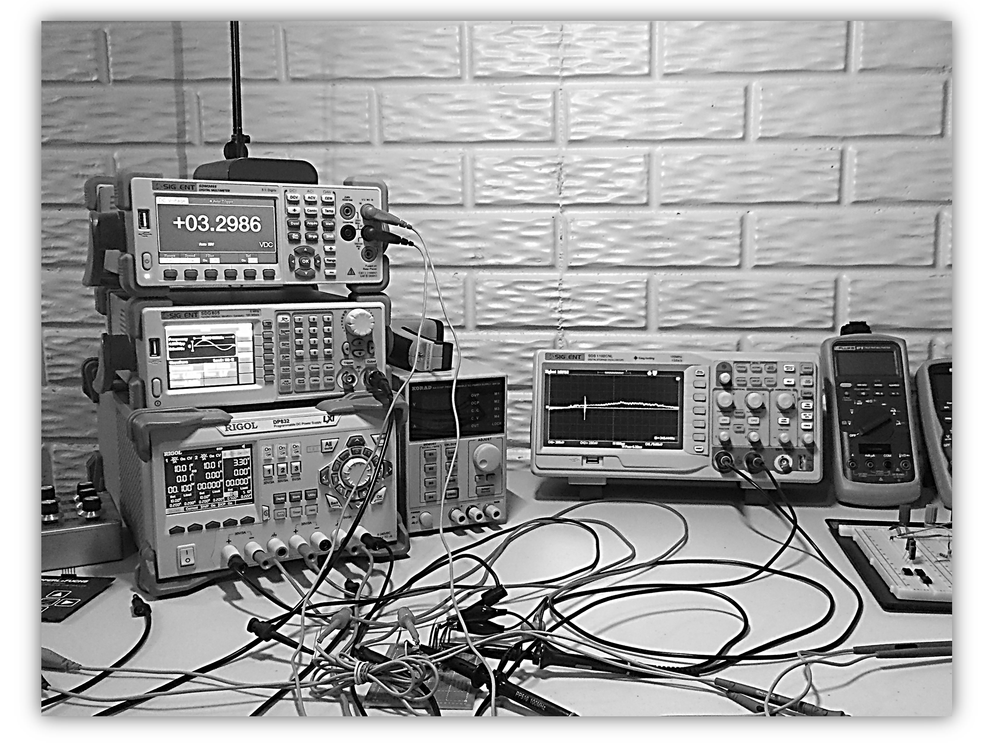
For this example, I will be using the following equipment:
Click on each of the instruments to see the python functions I have written for them. The function prototypes can be found here.
Note that if you happen to have the same instruments as me and would like to use my code, you may have to change the resource name for your instrument:
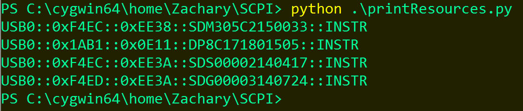
I have written a script that will output the resource names for all of your connected instruments. It can be found hereon my github page.
Here is an example of what the output might look like when you run the script:
For this test, I will need to be able to remotely carry out the following functionalities:
Set power supply voltage
Set power supply over current protection
Toggle power supply channels on/off
Set waveform generator amplitude and frequency
Toggle waveform generator channel on/off
Measure peak to peak voltages from both channels of the oscilloscope
Once all of these have been written in, I can call these functions sequentially in the test script just as if I were preforming the task by hand.
The test script for characterizing the gain of the amplifier can be found here.
To summarize what will happen in this test:
Over current protection is set and the amplifier is given power from two channels of the power supply.
The amplitude of the input signal is set to 4 mV and the frequency is set to 1 Hz.
A peak-to-peak voltage measurement is taken by the oscilloscope of both the input and output signals of the amplifier.
The frequency is increased by 100 Hz, and the input and output peak-to-peak voltage is measured again.
This process is repeated until the frequency of the input signal has reached 1 MHz.
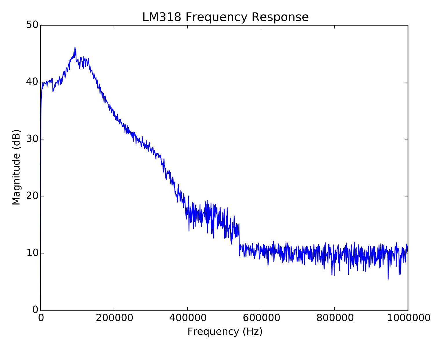
Once the test has been completed, the raw data is automatically exported into an Excel file in addition to generating a scaled plot with a title and axis labels and then saving this plot as a PDF file. The auto-generated plot is so that I can easily visualize the data to see if what I collected is meaningful.
Turn off the power supply and waveform generator’s outputs.
It should also be noted that calculations can be performed on the data as it is collected. In this example, I am calculating the gain in dB after each input and output peak-to-peak voltage reading is taken, and then storing the result in an array.
Here is what the auto-generated plot looks like:
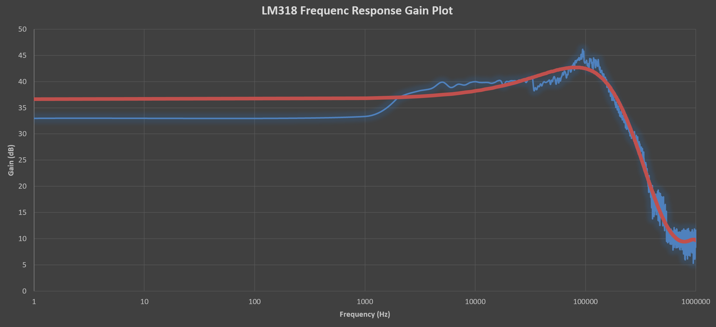
I now have an idea of what my data looks like and every data point has been saved into an Excel spreadsheet. Now I can do what ever I want with the data — create more plots, add trend lines, etc…
Conclusion Test automation is a valuable skill to have in your tool belt. If you are a designer, chances are you are going to be spending a lot of time validating your design requirements. While the programming requires a significant amount of effort in the front end, you will surely save time in the long run and become a more capable designer and tester.