
Abstract
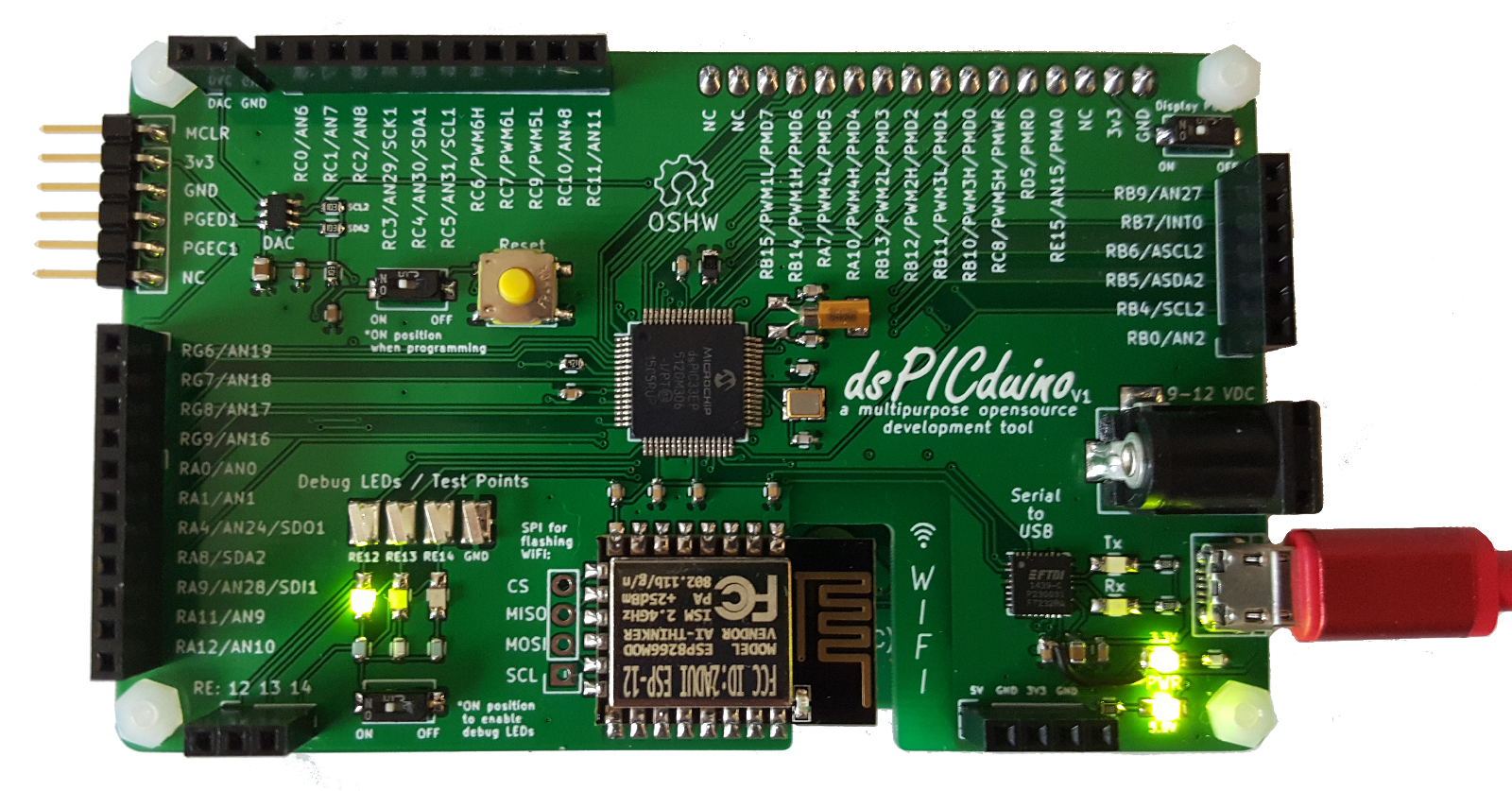
As an attempt to start an open source project, I’ve designed a general purpose development board featuring Microchip’s dsPIC along side the ESP8266.
The Arduino has gained immense popularity due to its ability to allow hobbyists to incorporate embedded control/processing into their projects. I am grateful for the Arduino, as it inspired me to explore the field of embedded hardware and software design.
The purpose of the dsPICduino is similar to the purpose of the Arduino — that is, it serves as both a learning and development platform for the aspiring embedded developer. The dsPICduino offers a more immersive embedded experience by stepping away from the layers of abstraction provided by the Arduino ecosystem.
Features of the dsPICduino
- WiFi station capability (ESP8266 running NodeMCU)
- Break out of 42 general purpose digital I/O pins
- Break out 15 analog channels
- Break out of 12 high speed PWM channels
- 12 bit DAC (accessable via I2C)
- Break out of hardware SPI and I2C busses
- USB to serial converter (FTDI)
- Easily integrated to character/matrix displays via Parallel Master Port
- Debugging LEDs and test points
- Secondary tuning fork oscillator (32.768 kHz) for real time clock/calendar
- Power over USB or DC barrel jack
Features of the dsPIC
- Up to 70 MIPS (140MHz with PLL)
- DSP math function library
- Dual 40-bit accumulators, single-cycle 16 x 16 MAC, 40-bit barrel shifter, dual operand fetches
- DMA
- 10nA sleep current
- (9) 16-bit timers, or (1) 16-bit and (4) 32-bit timers
- Hardware Output Compare and Input Capture
- Motor Control Peripherals with fast and flexible PWMs
- 1MSPS 12bit ADC or (32) multiplexed analog inputs @ 10-bit
- SPI, I2C, CAN, UART
Demonstrations
With WiFi and USB incorporated into the dsPICduino, projects can be easily integrated into IoT applications. The following GIFs demonstrate utilization of the USB to serial converter allowing a user to configure the WiFi module to connect to their local network.
Once connected, the WiFi module acts as a station on the network with internet access. From here, HTTP GET requests can be made to then scrape and parse HTML for weather and UNIX time data.
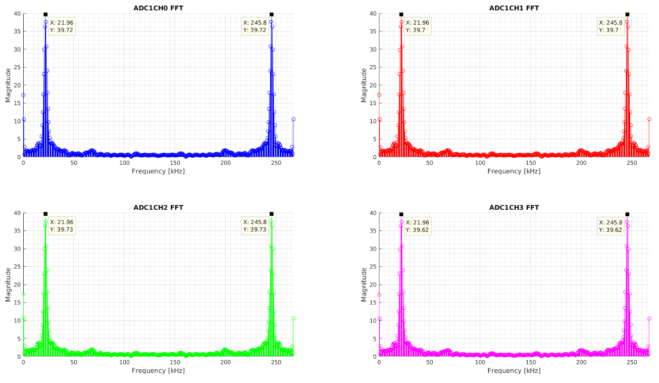
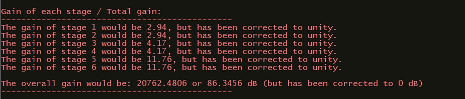
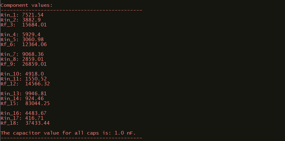
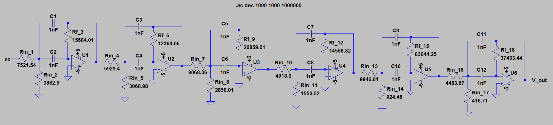
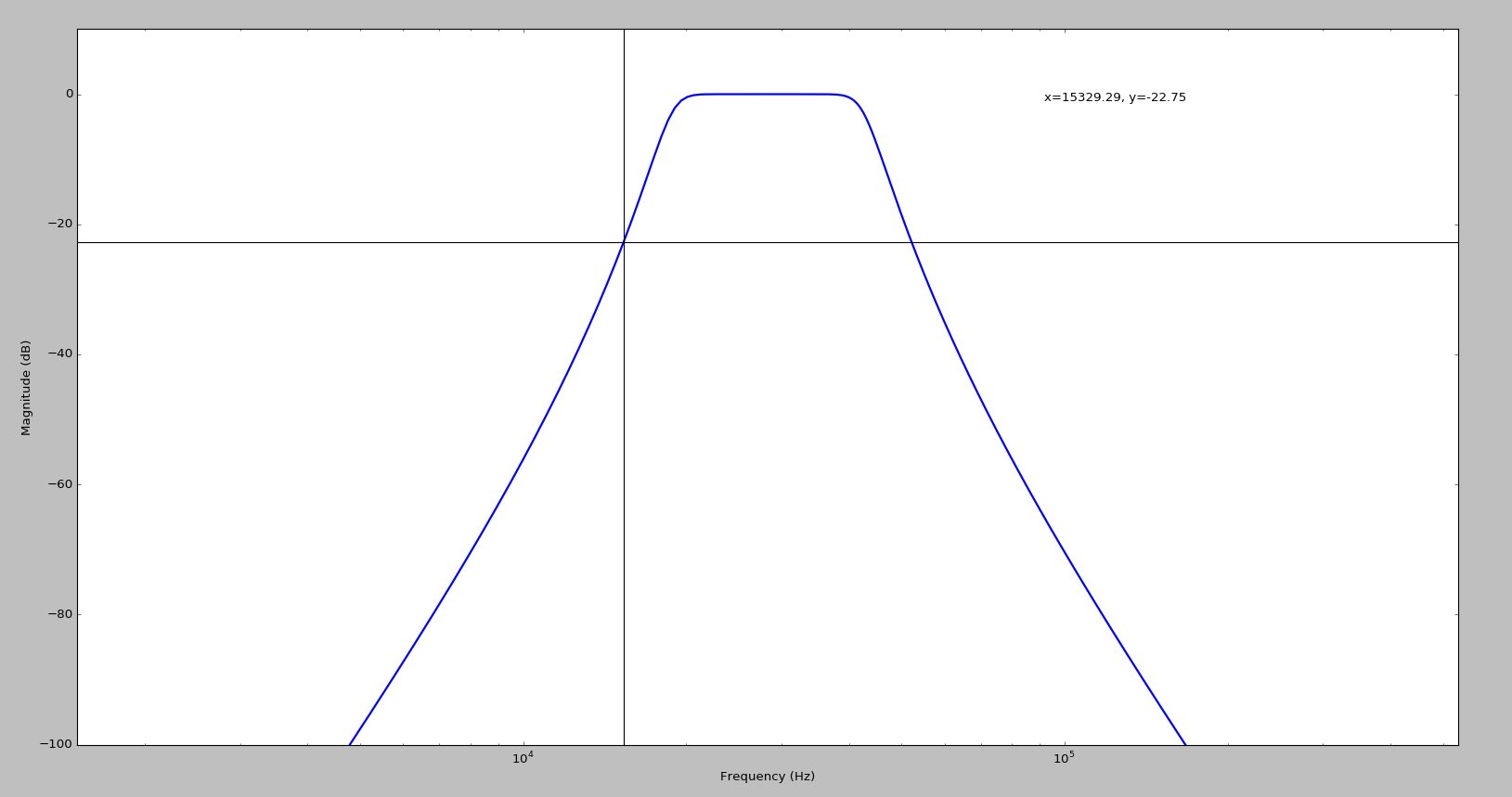
All of this functionality is complemented by the dsPIC’s ability to perform DSP functions that are useful in signal processing applications such as audio, motor control, and RF.
The following image is a plot of the magnitude of the complex array returned by the dsPIC (off loaded through the debugger) when using it to compute the FFT of a sampled 22 kHz sinusoidal signal on 4 analog channels.
Code
Link to dsPICduino github repository
Hardware
3D Board model: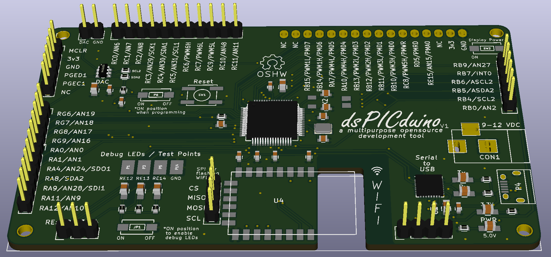
2D Board layout: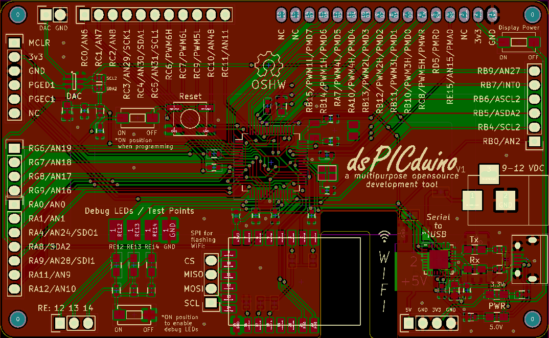
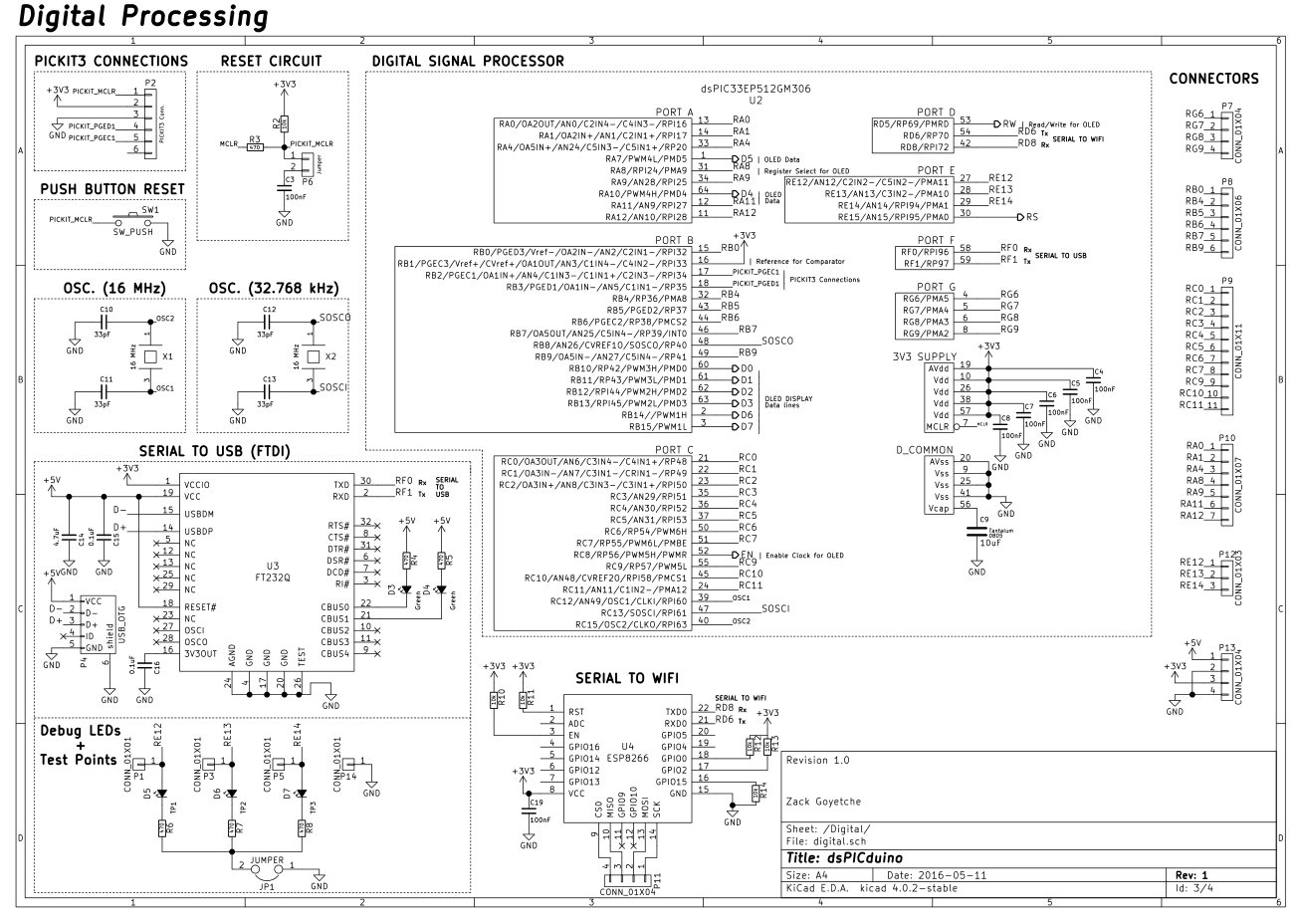
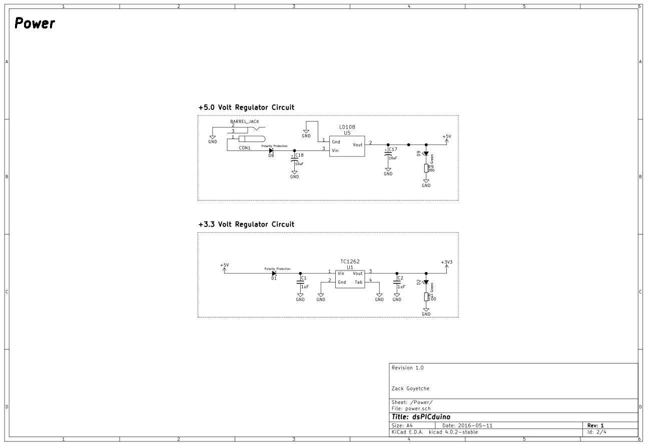
Schematic:
Gerber files:
dsPICduino Gerbers Zipped
BOM:
dsPICduino Bill of Material .xlsx file
